Pressure relief valve

A pressure reducing valve and valve body technology, which is applied in the field of pressure reducing valves, can solve problems such as difficulty in assembling and attaching pressure reducing valves, and achieve the effect of reliable functionality and good reset force

Active Publication Date: 2015-10-28
NEOPERL
View PDF7 Cites 6 Cited by
  • Summary
  • Abstract
  • Description
  • Claims
  • Application Information

AI Technical Summary

Problems solved by technology

This also makes the assembly of the previously known pressure relief valves additionally difficult.

Method used


Image

  • Pressure relief valve
  • Pressure relief valve
  • Pressure relief valve

Examples


Embodiment Construction

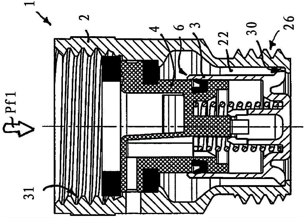
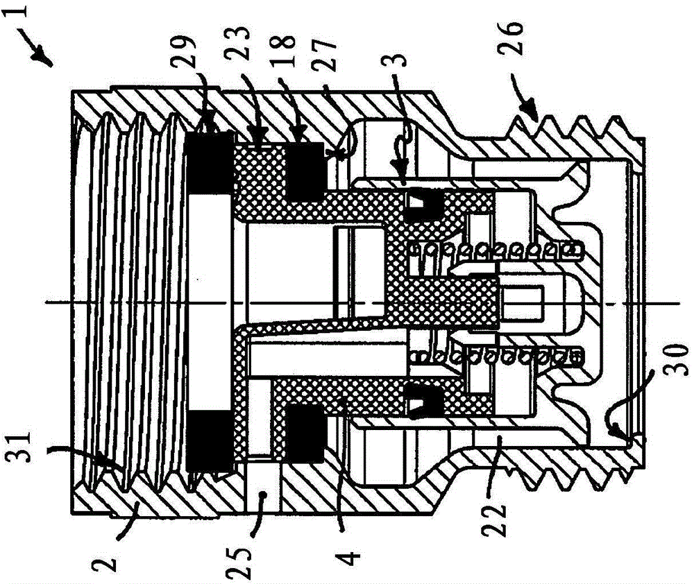
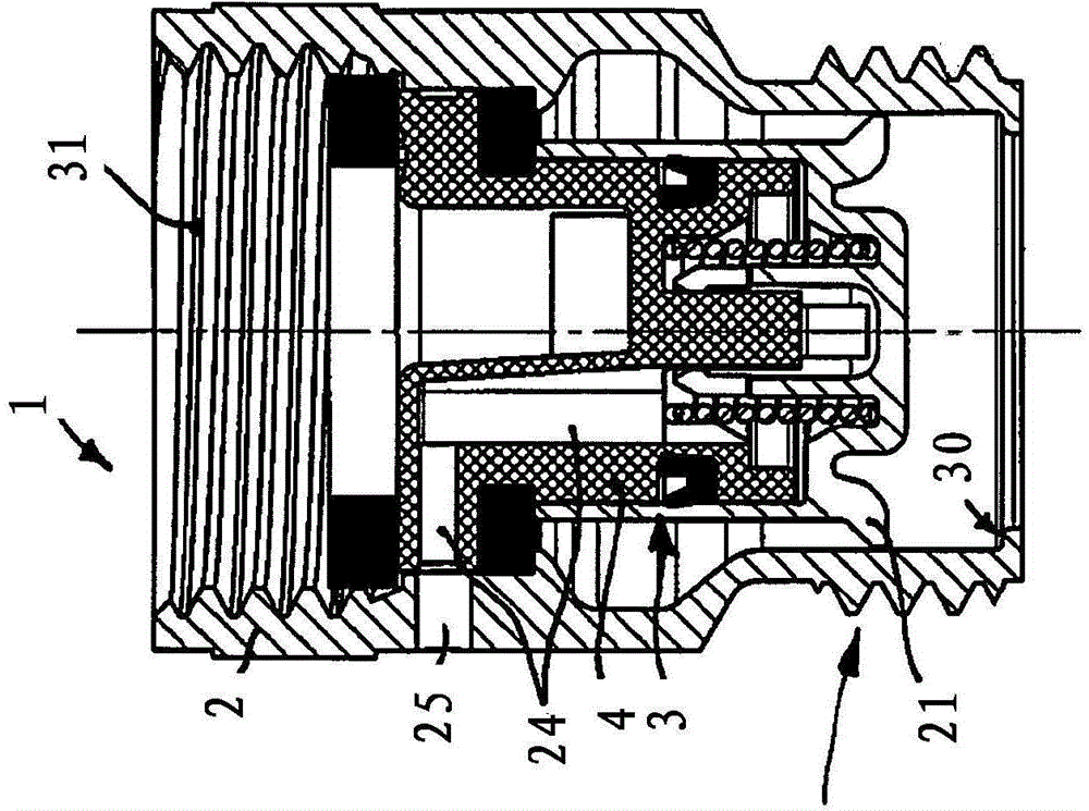
[0029] exist Figures 1 to 8 shows a pressure reducing valve 1 through which flow is made in the direction of the arrow Pf1 , which can be inserted, for example, into a water line in order to limit the water pressure in the line section downstream of the pressure reducing valve to a defined maximum value. The pressure relief valve 1 has a valve housing 2 which can be plugged or interconnected into a fluid line. A pot-shaped valve body 3 is arranged in the housing interior of the valve housing 1 . The pressure relief valve 1 has a valve holder 4 in which at least one throughflow channel 5 is arranged. If the conduit cross-section of the downstream conduit section contracts and the water pressure increases there, the displaceably guided valve body 3 is controlled by the pressure of the medium flowing through it. figure 1 The open position shown in the movement overcomes the reset force of at least one reset element to the image 3 In the closed position shown in , in this clo...


PUM


Abstract

The present invention relates to a pressure relief valve (1) comprising a valve housing (2), in which housing interior a valve support (4) is provided which has at least one through flow channel (5), and comprising a cup-shaped valve body (3) which is displaceably guided against a return force from an open position into a closed position. In the closed position, the valve body (3) abuts against a valve seat (7) provided on the valve support (4) with the circumferential edge (6) of its cup shape, in such a way that the valve body (3) blocks at least one channel opening (8) of the at least one through flow channel (5). The pressure relief valve (1) according to the invention is characterized in that at least one holding sleeve (9) is arranged on the valve support (4) or on the valve body (3), into which holding sleeve a retaining pin (10), provided on the valve body (3) or on the valve support (4) respectively, projects, and that a stop (11) is provided on the inner circumference of the holding sleeve (9), which stop interacts with a counter stop (12) on the outer circumference of the retaining pin (10) in such a way that, in an open position of the pressure relief valve (1), the stop (11) and the counter stop (12) limit the sliding distance of the valve body (3) relative to the valve support (4).

Description

technical field [0001] The invention relates to a pressure reducing valve comprising a valve housing, a valve holder is arranged in the housing inner space of the valve housing, the valve holder has at least one flow channel, and the The pressure relief valve comprises a cup-shaped valve body, which is guided from an open position displaceably against a restoring force into a closed position, in which the valve body rests with its cup-shaped peripheral edge on the The valve seat is arranged on the valve carrier such that the valve body closes at least one channel opening of the at least one through-flow channel. Background technique [0002] Hygienic shower sprinklers with a shower head having a large-sized shower surface with a plurality of relatively small spray openings are gradually gaining importance. With the aid of such a shower spray device, shower water can be produced which is formed from a plurality of fine, filamentous individual jets. A disadvantage, however, ...

Claims


Application Information

Patent Timeline
Patent Type & Authority Applications(China)
IPC IPC(8): F16K17/04
CPCG05D16/106F16K17/04F16K1/126F16K27/02F16K31/1221F16K31/1223
Inventor M·方迈尔
Owner NEOPERL
Why Eureka
Try Eureka