Coiled tubing length measuring device

A technology of length measurement and oil pipe output device, applied in the direction of measurement device, instrument, etc., can solve the problems of large measurement error and oil pipe slippage length, etc., to avoid large measurement error and improve the effect of measurement length

Inactive Publication Date: 2015-10-28
THE 22ND RES INST OF CHINA ELECTRONICS TECH GROUP CORP
View PDF5 Cites 2 Cited by
  • Summary
  • Abstract
  • Description
  • Claims
  • Application Information

AI Technical Summary

Problems solved by technology

[0006] The main purpose of the present invention is to provide a coiled tubing length measuring device to solve the problem in the prior art that the coiled tubing length measuring device is easy to slip with the oil pipe and cause large length measurement errors

Method used


Image

  • Coiled tubing length measuring device
  • Coiled tubing length measuring device
  • Coiled tubing length measuring device

Examples


Embodiment Construction

[0025] It should be noted that, in the case of no conflict, the embodiments of the present invention and the features in the embodiments can be combined with each other. The present invention will be described in detail below with reference to the accompanying drawings and examples.

[0026] In order to enable those skilled in the art to better understand the solutions of the present invention, the following will clearly and completely describe the technical solutions in the embodiments of the present invention in conjunction with the drawings in the embodiments of the present invention. Obviously, the described embodiments are only It is an embodiment of a part of the present invention, but not all embodiments. Based on the embodiments of the present invention, all other embodiments obtained by persons of ordinary skill in the art without making creative efforts shall fall within the protection scope of the present invention.

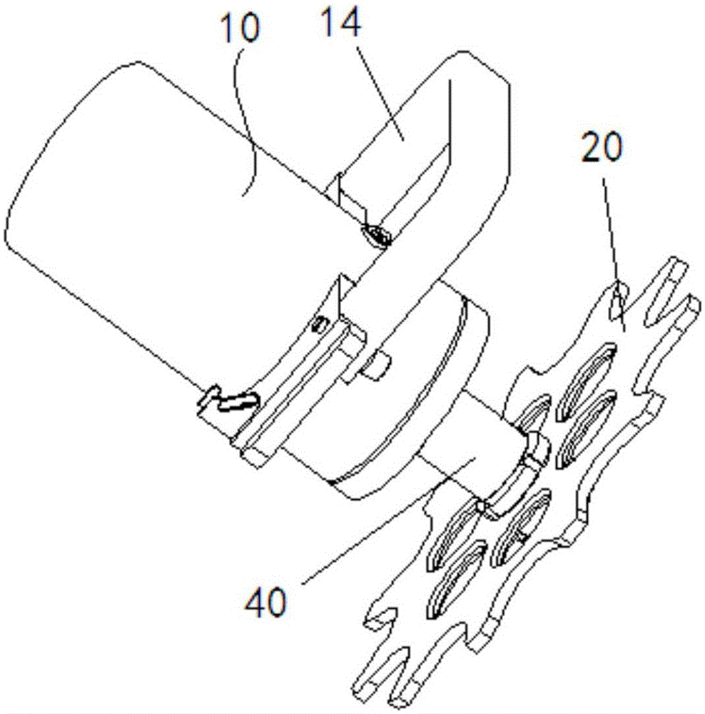
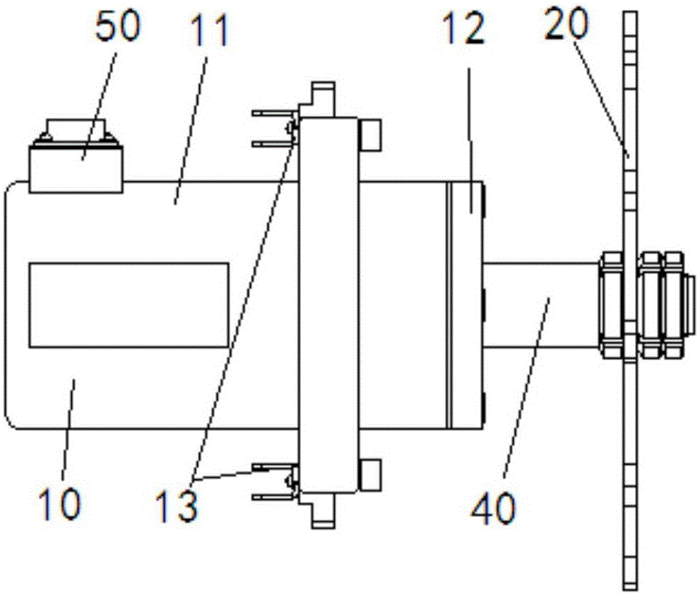
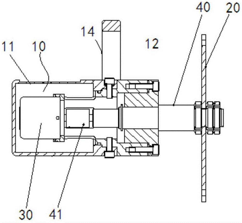
[0027] Such as Figure 1 to Figure 3 As shown,...


PUM


Abstract

The invention provides a coiled tubing length measuring device comprising an installing shell, a connector, a counter and a connecting shaft. The installing shell is used for installation and fixing with coiled tubing equipment. The connector is connected with the tubing output device of the coiled tubing equipment in a driving way. The counter is installed in the shell. The connecting shaft is connected with the connector and the input end of the counter. With application of the coiled tubing length measuring device, a problem of high length measurement error caused by the fact that the coiled tubing length measuring device and tubing are liable to slip in the prior art can be effectively solved.

Description

technical field [0001] The invention relates to the field of oil field technology, in particular to a coiled tubing length measuring device. Background technique [0002] Coiled tubing is a kind of equipment used in oil and gas well operations. The coiled tubing length measuring device is an important part of the coiled tubing equipment. Its main function is to measure the length of the coiled tubing running into or out of the oil well in real time during operation. . [0003] The existing coiled tubing machine length measuring device is composed of a roller, a roller assembly, a mechanical type, an electronic type, a spring, and a casing coaxially connected with the roller. When the tubing machine is in operation, the tubing wound on the drum passes through the device, so that the rollers in the device are pressed into contact with the tubing. The rollers rely on the friction between the tubing and the tubing to realize their own rotation when the tubing is lowered or lift...

Claims


Application Information

Patent Timeline
Patent Type & Authority Applications(China)
IPC IPC(8): G01B21/06
CPCG01B21/06
Inventor 方孟虎王强张宏斌李怀周成兴丽
Owner THE 22ND RES INST OF CHINA ELECTRONICS TECH GROUP CORP
Why Eureka
Try Eureka