Surrounding rock mining damage range segmentation test system

A technology of mining destruction and testing system, which is applied in geophysical measurement and instruments, can solve problems such as large blindness, expansion of borehole wall, and poor applicability of empirical formulas, so as to improve stability, reduce the number of pipelines, and solve the problems of The effect of intertwining multiple pipes

Active Publication Date: 2017-07-18
SHANDONG UNIV OF SCI & TECH
View PDF6 Cites 0 Cited by
  • Summary
  • Abstract
  • Description
  • Claims
  • Application Information

AI Technical Summary

Problems solved by technology

[0003] However, due to the complex site conditions, to a certain extent, the numerical simulation cannot reflect the site conditions well, and the blindness of the empirical formula is relatively large. As the mining depth increases, the applicability of the empirical formula becomes worse and worse.
First of all, due to the excessive number of pipelines working at the same time in the existing observation equipment, especially during the propulsion process, the problem of pipeline entanglement in the borehole is prone to occur. The observed water pressure is generally 0.1MPa, and the observed water source pressure in the borehole should not be too high, otherwise, it will cause expansion of the original cracks in the borehole wall
Under the same external water source, how to make the plugging water source and the observation water source in the integrated observation equipment work at the same time under their respective pressures? Finally, because the drilling length is approximately 50-70m, the test site often uses a single-stage water injection observation instrument. Advance the measurement length (about 1m), too many advances will greatly increase the manual workload, which may affect the measurement accuracy
The prior art fails to solve the above three problems simultaneously

Method used


Image

  • Surrounding rock mining damage range segmentation test system
  • Surrounding rock mining damage range segmentation test system
  • Surrounding rock mining damage range segmentation test system

Examples


Embodiment Construction

[0032] The present invention will be described in further detail below in conjunction with specific embodiments.

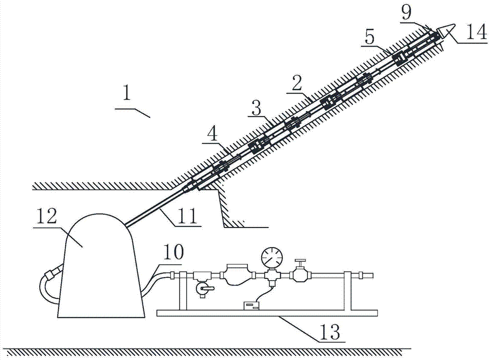
[0033] Surrounding rock mining damage range segmentation test system of the present invention, such as figure 1 As shown, it mainly includes a plugging system, a guiding system, a supply propulsion system, a pressure conversion system and an observation system, wherein the supply propulsion system includes a water injection operation platform 13, a return water pressure gauge, an electronic recorder, a drilling rig 12 and a drill pipe 11, The drilling rig is connected to the water injection console through the high-pressure hose 10. The function of the water injection console is to provide high-pressure water source to the connecting pipe 4 through the high-pressure hose. The electronic recorder is installed on the water injection console to record the flow rate of the electronic flowmeter. Parameters, the return water pressure gauge is used to correct and detect ...


PUM


Abstract

The invention discloses a segmental testing system for mining damage of surrounding rock, which belongs to the technical field of measuring the damage range of rock mass on the roof and floor of mines. It solves the problems of one-time plugging and multi-segment measurement, plugging and leakage measurement integration and internal water pressure conversion measurement of mine roof and floor rock mass observation equipment. It includes a blocking system, a guiding system, a supply propulsion system and a pressure conversion system. The blocking system includes a first blocking unit, a second blocking unit and a third blocking unit, and each blocking unit includes a leaking pipe and a connection At the tubular joints at both ends of the leaking pipe, a connecting pipe is arranged between the adjacent blocking units, and the two ends of the connecting pipe are respectively connected to the tubular joints of the adjacent sealing units, and the outer periphery of the leaking pipe between the two tubular joints A blocking capsule is provided, and a certain blocking space is formed between the blocking capsule and the leaking pipe. The test system can simultaneously realize the multi-stage measurement of plugging, the integration of plugging and leak detection, and the pressure conversion from plugging high-pressure water sources to observing low-pressure water sources.

Description

technical field [0001] The invention belongs to the technical field of measuring the damage range of rock mass on the roof and floor of a mine, and in particular relates to a segmented testing system for the damage range of surrounding rock mining. Background technique [0002] The measurement of the damage range of rock mass on the roof and floor of mine is an important parameter to indicate the occurrence state of coal rock. It is a key basic parameter in the study of mine water prevention and control. Therefore, to study the formation of water-conducting channels in mining surrounding rocks, it is necessary to grasp the movement rules of rock strata and determine the damage range of roof and floor rock mass. Numerical simulation, empirical formula prediction, field measurement and other methods are usually used. [0003] However, due to the complex site conditions, to a certain extent, the numerical simulation cannot reflect the site conditions well, and the blindness of...

Claims


Application Information

Patent Timeline
Patent Type & Authority Patents(China)
IPC IPC(8): G01V9/00
CPCG01V9/00
Inventor 刘伟韬赵春波宋文成王建宁赵吉园
Owner SHANDONG UNIV OF SCI & TECH
Why Eureka
Try Eureka