Method for testing contact rigidity of rock discontinuity structural plane, and apparatus thereof

A contact stiffness and structural surface technology, applied in the fields of geology and mechanics, can solve problems such as large errors, inability to measure the contact stiffness of large structural surfaces, and large disturbance of structural surfaces

Active Publication Date: 2015-10-28
INST OF MECHANICS - CHINESE ACAD OF SCI
View PDF6 Cites 10 Cited by
  • Summary
  • Abstract
  • Description
  • Claims
  • Application Information

AI Technical Summary

Problems solved by technology

[0004] The above method of testing the structural surface contact stiffness can only be done in the laboratory, so on-site sampling and specimen processing are required, the process is relatively complicated, the structural surface is greatly disturbed, and the influence of the original rock stress on the structural surface stiffness cannot be reflected
In addition, due to the limitation of experimenta

Method used


Image

  • Method for testing contact rigidity of rock discontinuity structural plane, and apparatus thereof
  • Method for testing contact rigidity of rock discontinuity structural plane, and apparatus thereof
  • Method for testing contact rigidity of rock discontinuity structural plane, and apparatus thereof

Examples


Embodiment 1

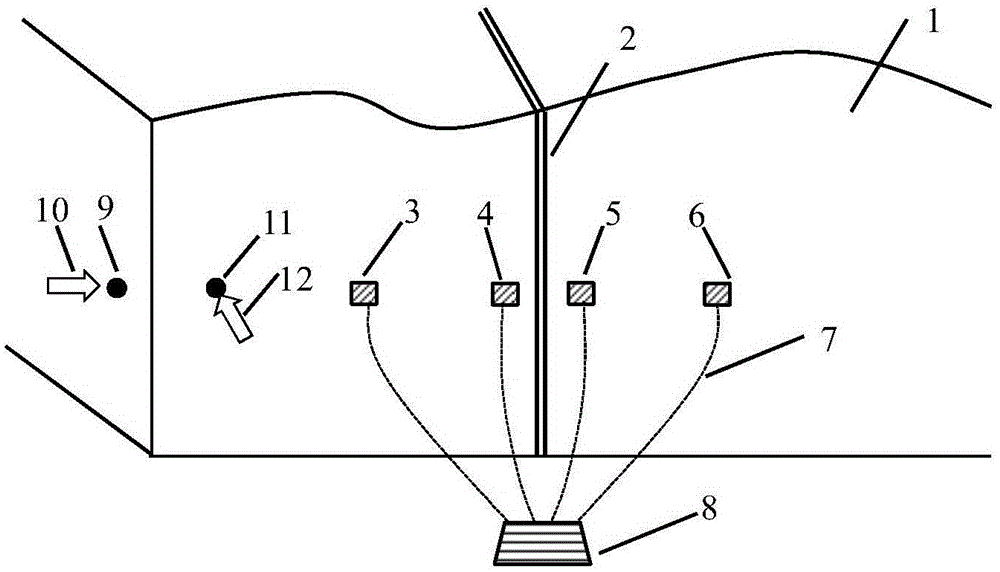
[0055] Test and analyze the normal contact stiffness and tangential contact stiffness of the limestone structural plane in an open-pit mine. The experimental process is as follows: figure 1 shown. Select an area with better outcropping on the structural surface 2, and use a brush to clean the structural surface 2 and the complete rock mass 1 on both sides to remove floating dust and loose broken bodies on the surface. Using gypsum, fix the vibration acceleration sensors 3 to 6 on the complete rock mass 1 on both sides of the structural surface 2 at a certain distance. The distances from acceleration sensors 4 and 5 to the structural surface 2 are both 5 cm, and the distances from acceleration sensors 3 and 6 to the structural surface are both 50 cm. Use the data line 7 to connect the acceleration sensors 3 to 6 to the acquisition instrument 8, and turn on the acquisition instrument 8 to make it in the sampling state. Select two hammering points, hammering point 9 and hammeri...

Embodiment 2

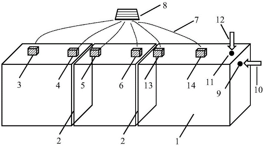
[0057] The normal contact stiffness and tangential contact stiffness were tested and analyzed for the granite structural surface exposed by the excavation of a certain slope. The experimental process is as follows: figure 2 shown. Clean up the two structural surfaces 2 exposed by the excavation and the surrounding complete rock mass 1 to remove surface impurities. Use expansion bolts to install the vibration velocity sensors 3, 4, 5, 6, 13, 14 to the corresponding positions of the complete rock mass 1 around the structural surface 2; and ensure that the sensors 3, 4, 5, 6, 13, 14 are on a straight line , and perpendicular to the structural plane 2. The distances from sensor 4 and sensor 5 to the left structural surface 2 are both 10 cm, and the distances from sensor 6 and sensor 13 to the right structural surface 2 are also 10 cm. Between sensor 3 and sensor 4, between sensor 5 and sensor 6, The distance between sensor 13 and sensor 14 is 5 m. The sensors 3, 4, 5, 6, 13, 1...


PUM


Abstract

The invention discloses a method for testing the contact rigidity of a rock discontinuity structural plane. The method comprises the following steps: 1, selecting a test area; 2, installing vibration sensors; 3, starting a collecting instrument to make the collecting instrument in a sampling state; 4, hammering one side of the rock discontinuity structural plane, and adjusting the hammering direction to generate longitudinal waves and transverse waves vibrating along the line direction of the vibration sensors; 5, recording through the collecting instrument; 6, calculating the wave velocity of the longitudinal waves, the wave velocity of the transverse waves, the time consumption of the longitudinal waves passing through the structural plane and the time consumption of the transverse waves passing through the structural plane; 7, calculating the elastic modulus and the Poisson's ratio of a complete rock; 8, carrying out inversion analysis by means of a value technology, and establishing a value model similar to the test area; and 9, applying impact load to one side of the value model, and continuously adjusting the normal contact rigidity and the tangential contact rigidity of the structural plane in the value model to obtain the contact rigidity of the structural plane of the test area. The invention also provides an apparatus adopting the method.

Description

technical field [0001] The invention belongs to the technical field of geology and mechanics, and in particular relates to a method for testing the contact stiffness of a rock mass structural surface and a device using the method. Background technique [0002] There are a large number of structural planes such as faults, joints, and cleavages in the geological body. The mechanical properties of the above structural planes will directly affect the stability of the geological body and the potential failure mode of instability. The mechanical properties of the structural surface include the normal contact stiffness, tangential contact stiffness, cohesion, internal friction angle and tensile strength of the structural surface. Among the above-mentioned mechanical properties of the structural surface, the contact stiffness of the structural surface not only affects the static stress-strain relationship of the geological body, but also directly affects the dynamic mechanical behav...

Claims


Application Information

Patent Timeline
IPC IPC(8): G01N19/00
Inventor 冯春李世海郭汝坤乔继延
Owner INST OF MECHANICS - CHINESE ACAD OF SCI
Why Eureka
Try Eureka