Motor vehicle door lock

A technology of motor vehicle door locks and rotating lock forks, which is applied in vehicle locks, building locks, mechanical equipment, etc.

Active Publication Date: 2017-07-07
KIEKERT AG
View PDF2 Cites 0 Cited by
  • Summary
  • Abstract
  • Description
  • Claims
  • Application Information

AI Technical Summary

Problems solved by technology

[0007] Therefore, the technical problem to be solved by the present invention is to continue to improve the motor vehicle door lock of the design described at the beginning, so that the noise situation of the locking mechanism is improved as a whole, wherein the focus is on reducing the noise that may occur when lifting the locking pawl from the rotary lock fork. keep to a minimum

Method used


Image

  • Motor vehicle door lock
  • Motor vehicle door lock

Examples


Embodiment Construction

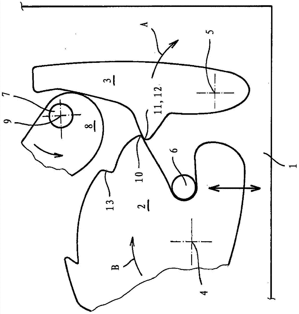
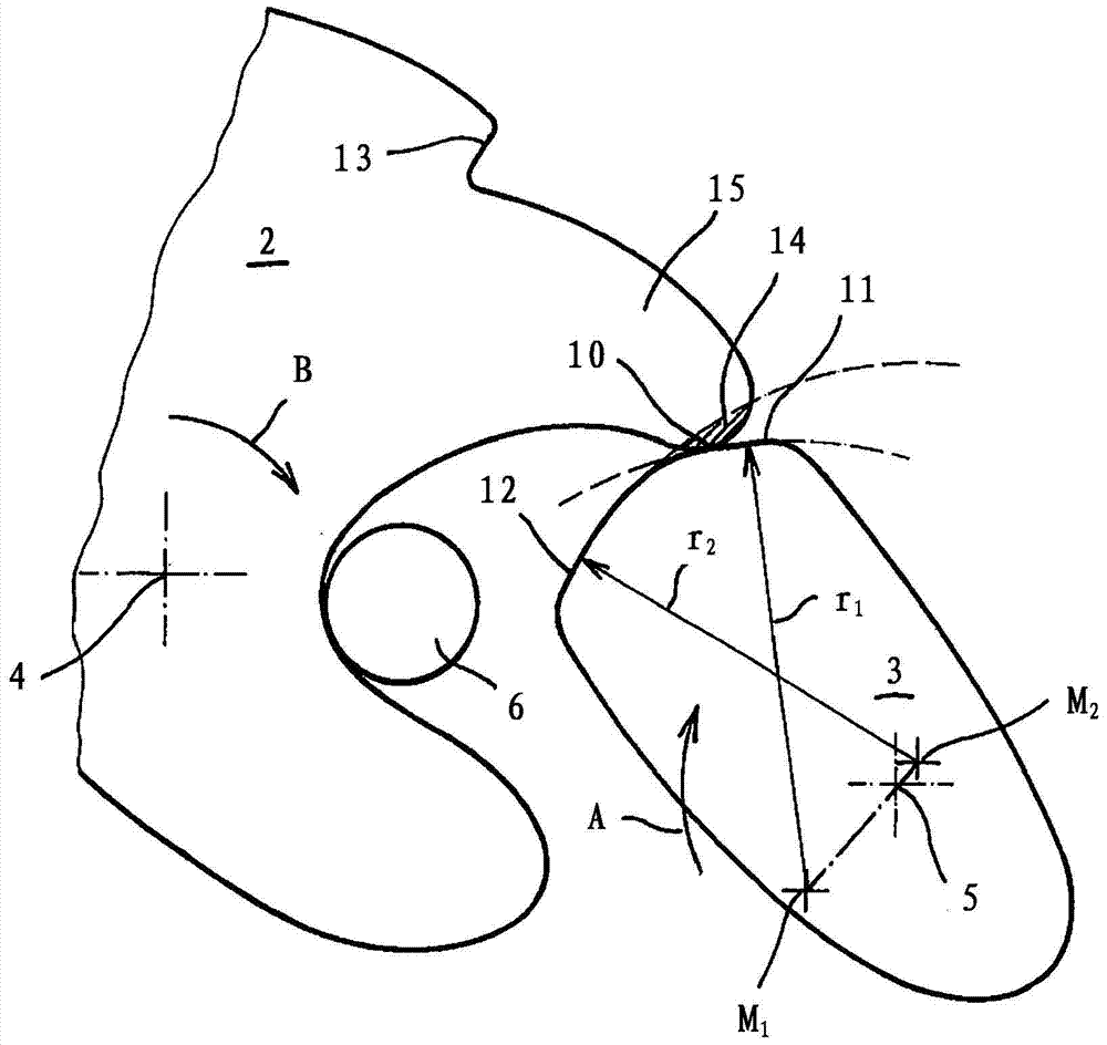
[0023] figure 1 A motor vehicle door lock is shown in , which has a lock box 1 in which a locking mechanism 2 , 3 comprising a rotary locking fork 2 and a pawl 3 is mounted. The rotary shaft 4 corresponds to the rotary lock yoke 2 , while the pawl 3 is supported in a swingable manner about a rotary shaft 5 . In addition, the locking pin 6 can be seen.

[0024] exist figure 1 The locking mechanism 2, 3 is shown in the locked state. In order to open the locking mechanism 2 , 3 , the drive unit 7 , 8 (but not limited to the drive unit) acts on the pawl 3 in this exemplary embodiment. The drive unit 7 , 8 consists, for example, of a motor or electric motor 7 and an actuating cam 8 acted upon by the motor 7 . The actuating cam 8 is generally helical, so that rotation about a corresponding axis 9 by means of the motor 7 is responsible for lifting the locking pawl 3 from the rotary locking fork 2 . In fact, in the locked state of the locking mechanism 2 , 3 shown, the rotary loc...


PUM


Abstract

The present invention relates to a motor vehicle door lock, which has a locking mechanism comprising a rotating lock fork (2) and a locking claw (3), wherein, in the locking state of the locking mechanism (2, 3), the locking contour (11, 12) of the locking claw (3) is attached to the locking contour (10, 13) of the rotating lock fork (2), wherein the latching profile (11,12) is designed as a two-piece and has a holding profile (11) and an open profile (12).

Description

technical field [0001] The invention relates to a motor vehicle door lock having a locking mechanism comprising a rotary locking fork and a locking pawl, wherein in the locked state of the locking mechanism, the locking pawl rests with its locking contour on the locking contour of the rotary locking fork. Background technique [0002] The locking mechanism of a motor vehicle door lock is the heart of the lock, since the final locking mechanism is responsible for locking and holding the corresponding motor vehicle door relative to the motor vehicle body. For this purpose, the locking mechanism comprising the rotary lock fork and the pawl is designed to be solid and usually made of steel in order to be able to withstand the great forces occurring in this position. In fact, for example a motor vehicle door lock with a locking mechanism located therein is mounted inside the vehicle side door and typically interacts with a latch / stop on the vehicle body such as a B-pillar. [00...

Claims


Application Information

Patent Timeline
Patent Type & Authority Patents(China)
IPC IPC(8): E05B85/26
CPCE05B77/36E05B85/26Y10T292/1075E05B79/10E05B85/243
Inventor T·班德尔A·汉德克M·奥赫特洛普M·赫尔曼A·索尔巴赫
Owner KIEKERT AG
Why Eureka
Try Eureka