
Feed pump

A feed pump and oil technology, applied in the direction of pumps, pump components, cross-flow pumps, etc., can solve the problems of reducing the working efficiency of the feed pump, strong noise, etc., to achieve simple rotation ability and axial movement ability, low click noise Effect

Inactive Publication Date: 2002-08-28
SIEMENS AG
View PDF0 Cites 3 Cited by
  • Summary
  • Abstract
  • Description
  • Claims
  • Application Information

AI Technical Summary

Problems solved by technology

[0003] A disadvantage of the known feed pump is that positioning tolerances and inclination angles of the shaft relative to the housing cause the impeller to rub against the housing
However, this friction produces strong noise and even reduces the efficiency of the feed pump

Method used


Image

  • Feed pump
  • Feed pump
  • Feed pump

Examples


Embodiment Construction

[0020] Description of preferred embodiments

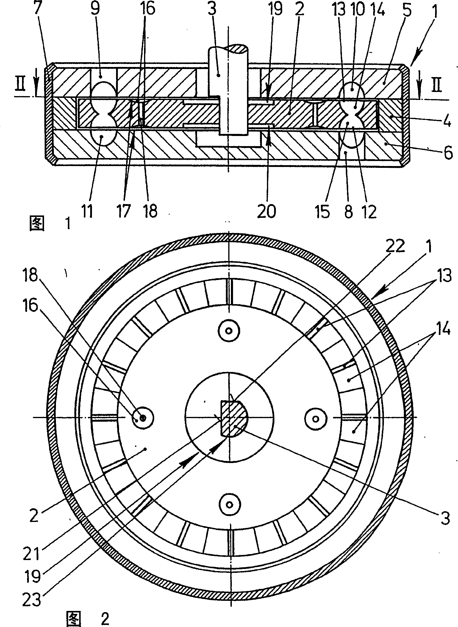
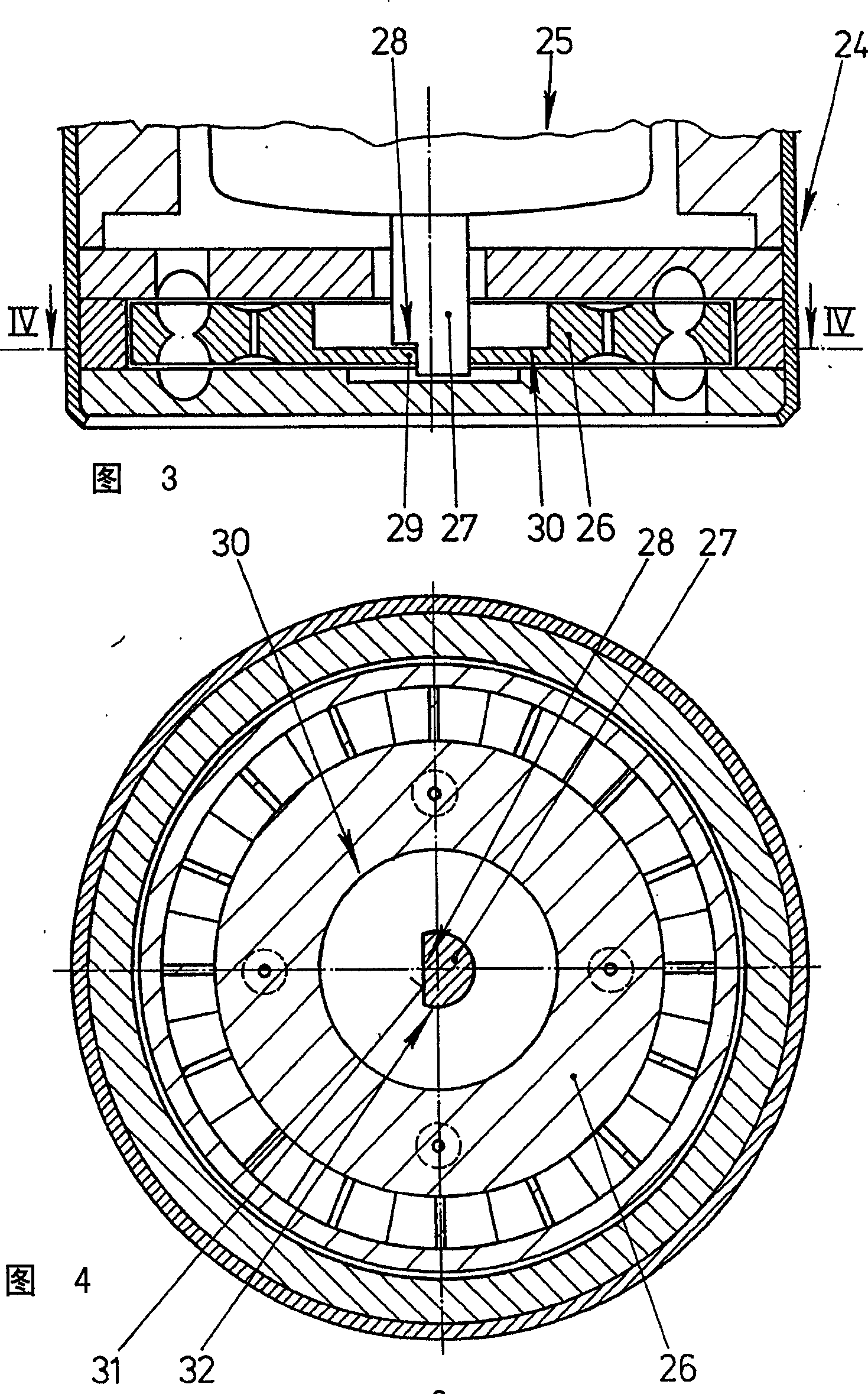
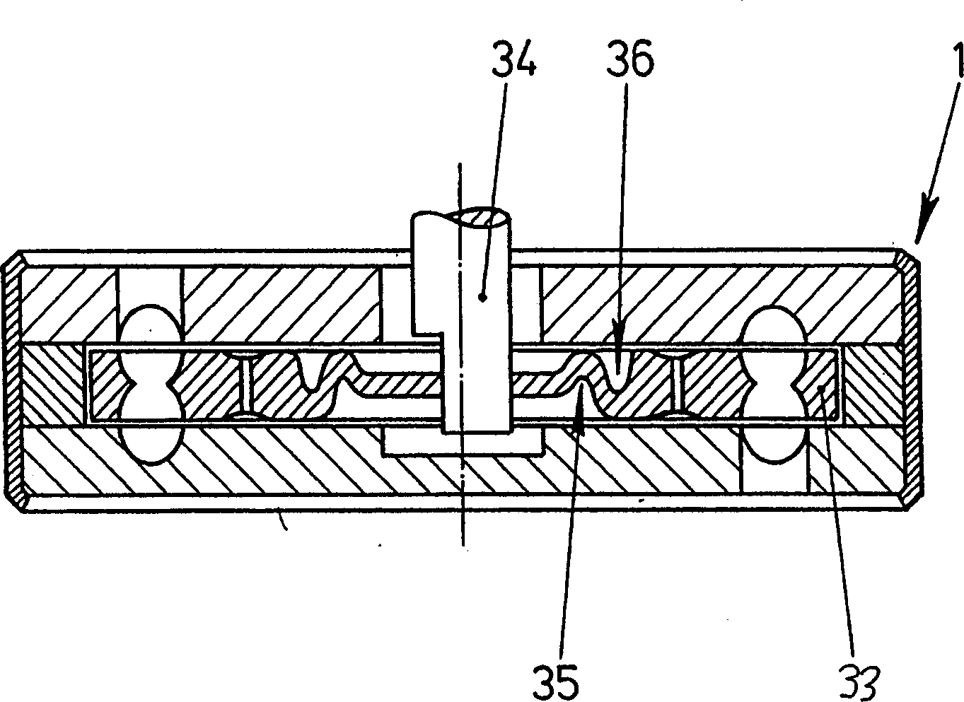
[0021] FIG. 1 shows a sectional view of a feed pump according to the invention, which is designed as a side channel pump and has an impeller 2 rotatable in a housing 1 . The impeller 2 is mounted on a drive shaft 3 fixedly with respect to the direction of rotation but slightly displaceable axially. The shaft 3 can be designed, for example, as the shaft of an electric motor (not shown). The housing 1 has two shell parts 5, 6 kept at a distance from each other by a ring 4 and a thin metal strip 7 rolled up on the edges of the shell parts 5, 6 in order to pretension the shell parts 5, 6 Tight on circle 4. An inlet flow channel 8 is arranged in one of the shell parts 6 , while the other shell part 5 has an outlet flow channel 9 . The inlet flow channel 8 and the outlet flow channel 9 are in each case connected to partial annular flow channels 10 , 11 . The impeller 2 has vane chambers 14 , 15 delimited by guide vanes 12 , 13 in the...


PUM


Abstract

In feed pumps designed as side channel pumps, the impeller (2) is supported such that it can rotate slightly relative to the shaft (3) about an axis transverse to the shaft (3). The impeller (2) can thus be adapted to the tolerances of the casing (1). Thus, the impeller (2) is prevented from rubbing against the casing (1). As a result, the feed pump produces very little noise.

Description

technical field [0001] The invention relates to feed pumps, in particular feed pumps for delivering oil from the fuel tank of motor vehicles or for supplying washer fluid for windshield washer systems, which have a drive shaft fixedly mounted with respect to the direction of rotation The impeller and a housing are situated opposite the impeller subregion with a slight gap. Background technique [0002] Such feed pumps are mostly designed as peripheral vane pumps or side channel pumps and are known from practice. In these pumps, the housing usually has two shell parts with grooves for the impellers. In the radially outer region of the impeller near the guide vanes, a very small sealing gap is provided between the impeller and the housing. An axial plain bearing is also usually arranged in the sealing gap. [0003] A disadvantage of the known feed pump is that positioning tolerances and inclination angles of the shaft relative to the housing cause the impeller to rub agains...

Claims


Application Information

Patent Timeline
Patent Type & Authority Applications(China)
IPC IPC(8): F04D5/00F04D29/18
CPCF04D29/188F04D29/18
Inventor P·马克斯B·耶格尔
Owner SIEMENS AG
Learn More