Supercharge Your Innovation With Domain-Expert AI Agents!

Concrete screw

A concrete and screw technology, applied in the direction of screws, threaded fasteners, threaded products, etc., can solve problems such as inapplicability, and achieve the effect of simplifying installation and reducing forming resistance

Inactive Publication Date: 2015-10-28
HILTI AG
View PDF9 Cites 1 Cited by
  • Summary
  • Abstract
  • Description
  • Claims
  • Application Information

AI Technical Summary

Problems solved by technology

The screw with a drill point known from EP 1 738 844 A1 is not suitable for concrete substrates

Method used


Image

  • Concrete screw
  • Concrete screw
  • Concrete screw

Examples


Embodiment Construction

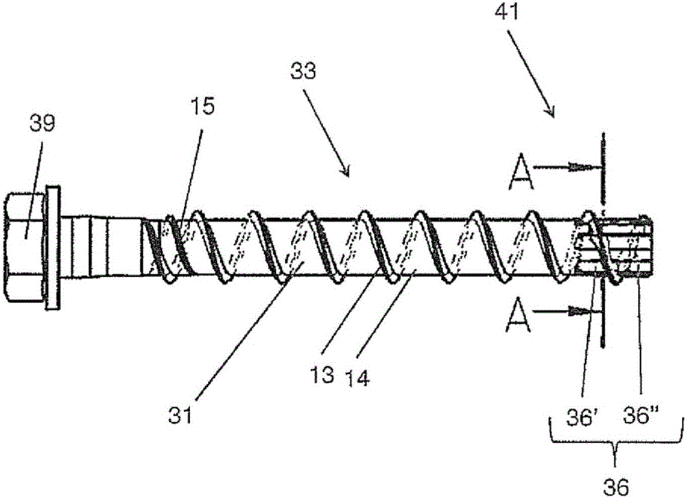
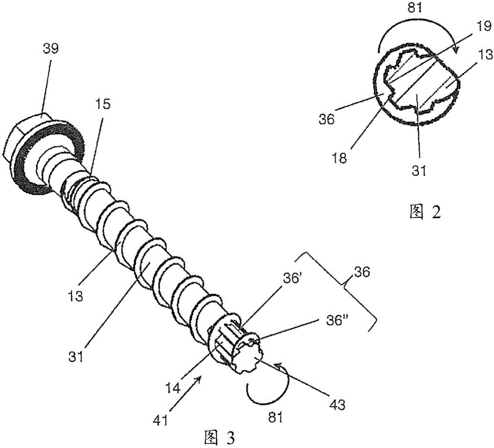
[0038] exist Figures 1 to 3 An embodiment of a concrete screw according to the invention is shown in . The screw has a cylindrical shank 31 , at one end of which a screw head 39 is formed, which has a polygonal configuration in the form of an external hexagon for a form-fitting, rotationally fixed connection to a mounting tool, for example a percussion screwdriver. At the opposite end of the screw head, ie in the region of the tip which is first introduced into the borehole, the shank of the concrete screw has a substantially flat end face 43 .

[0039] A thread 33 is formed on the outer side of the shaft 31 , the thread having a helical thread helix 13 and a helical thread root 14 delimited by the thread helix 13 . The thread root 14 is to be understood in particular as the surface area of ​​the shaft 31 which, viewed in the longitudinal direction of the shaft 31 , is bounded by axially opposite sides of the thread helix 13 .

[0040] The thread helix 13 starts in the regi...


PUM


Abstract

The invention relates to a concrete screw having a shaft (31) and a screw thread (33) arranged on the shaft and a threaded coil (13) and a threaded base (14). According to the invention, in the end area (41) of the shaft, inside the shaft, at least one cut-out recess (36) for widening a borehole is provided, said recess extending, at least in sections, inside the thread base without interrupting the threaded coil. The invention also relates to a flat die for producing said type of concrete screw. The invention further relates to a method for producing a concrete screw.

Description

technical field [0001] The invention relates to a concrete screw according to the preamble of claim 1 . Such concrete screws are constructed with a shank and a thread arranged on the shank, the thread having a thread helix and a thread root. The invention also relates to a thread rolling machine for manufacturing concrete screws according to the preamble of claim 11 , having a plurality of grooves for rolling threads. The invention also relates to a manufacturing method for a concrete screw according to the invention according to claim 14 . Background technique [0002] A concrete screw of this type is known, for example, from EP 2 233 757 A2. This document teaches that a cutting groove is provided in the outer side of the shank of the concrete screw, which is delimited by sharp edges. This edge can be used as a cutting edge, which can be used to enlarge the non-standard cylindrical drill hole by screwing in the screw. As a result of the cutting grooves, concrete screws ...

Claims


Application Information

Patent Timeline
Patent Type & Authority Applications(China)
IPC IPC(8): F16B25/00B21H3/02B21H3/06
CPCF16B25/0084B21H3/027B21H3/06F16B25/0026F16B25/0078F16B25/0068B21H3/04F16B25/103
Inventor T·诺伊迈尔M·温克勒G·多明利C·阿赫莱特纳
Owner HILTI AG
Features
  • R&D
  • Intellectual Property
  • Life Sciences
  • Materials
  • Tech Scout
  • Unparalleled Data Quality
  • Higher Quality Content
  • 60% Fewer Hallucinations
Learn More