Oscillation dusting machine

A technology for dust collectors and racks, which is applied in cleaning methods and utensils, chemical instruments and methods, etc., can solve the problems of offsetting time advantages, scattered cloth, and waste of labor costs.

Inactive Publication Date: 2015-11-04
LONGTEK SCI SUZHOU CO LTD
View PDF8 Cites 8 Cited by
  • Summary
  • Abstract
  • Description
  • Claims
  • Application Information

AI Technical Summary

Problems solved by technology

[0003] The existing technology is to use the cold air throwing of the dryer to remove the dust on the cloth surface. The disadvantage is that the neatly stacked cloth stacks after cutting are completely scattered after being thrown. Although this method can handle large quantities of products at one time, due to Manual re-stacking and packaging are required, which not only wastes a lot of labor costs, but also the subsequent re-stacking and packaging process offsets the time advantage brought by the previous large-batch processing, but will waste greater labor and time costs for re-stacking and packaging

Method used


Image

  • Oscillation dusting machine
  • Oscillation dusting machine

Examples


Embodiment Construction

[0018] The following will clearly and completely describe the technical solutions in the embodiments of the present invention with reference to the drawings in the embodiments of the present invention.

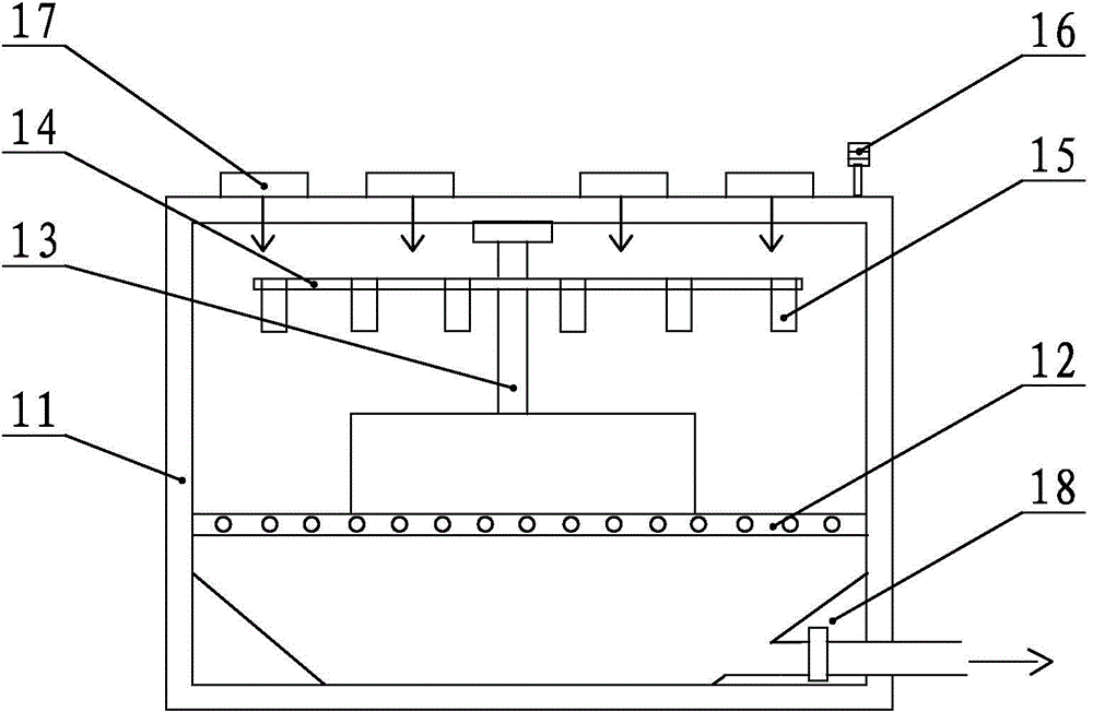
[0019] refer to figure 1 and 2 , the oscillating dust collector provided by the present invention includes a frame 11, and a dust falling plate 12 is horizontally arranged inside the frame 11 to divide the internal space into upper and lower parts. 14 is provided with a ring of vibrating devices 15 at equal intervals in the radial direction, and an indicator light 16 communicated with the vibrating device 15. The dust-falling plate 12 is provided with a through hole passing through the upper and lower side spaces; The air blower 17 is provided with an air suction blower 18 on the lower side of the dust falling board 12 .

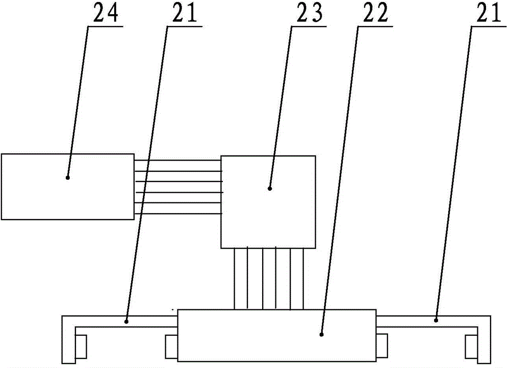
[0020] Wherein, the vibrating device 15 includes a transverse vibrating cylinder 24 and a longitudinal vibrating cylinder 23 which are connected to each o...


PUM


Abstract

The invention discloses an oscillation dusting machine. The oscillation dusting machine comprises a rack. A dust falling plate is horizontally arranged in the rack to divide the interior space into an upper part and a lower part. A rotary table is horizontally arranged in the space on the upper side of the dust falling plate through a rotating shaft, and the rotary table is at least provided with a circle of vibration devices in the radial direction and indicator lamps communicated with the vibration devices. A blowing draught fan corresponding to the rotary table is arranged on the upper side of the rotary table, and a suction draught fan is arranged on the lower side of the dust falling plate. Cut tidy cloth piles are clamped in cloth pile clamps and are subjected to alternative reciprocating vibration in longitudinal and transverse directions, and cloth clippings on the cloth piles are shaken off. Air with the clippings is pumped out of the oscillation dusting machine through the blowing draught fan on the top of the machine and the suction draught fan at the bottom of the machine. After an alarm is given after oscillation is finished, dust-free cloth piles are all in the place and can be directly packaged after being taken down, and the clipping removing efficiency can be greatly improved and the labor cost can be greatly reduced on the premise that the cleanliness of dust-free cloth is met and the cloth piles are kept tidy.

Description

technical field [0001] The invention relates to an oscillating dust collector. Background technique [0002] Dust-free wipes are widely used in semiconductor industry, panel industry, TP industry and solar energy industry. In the above-mentioned industries, dust-free wipes are directly used to wipe production equipment or products, and there are also low-level customer needs that do not use corresponding ones in clean rooms. Clean cloth products, and for products with relatively low cleanliness requirements, manufacturers generally do not need to clean and package the finished clean cloth in the clean room, and only need to remove the dust after the cutting is completed. It can meet the requirements of corresponding customers. [0003] The existing technology is to use the cold air of the dryer to remove the dust on the cloth surface. The disadvantage is that the neatly stacked cloth piles after cutting are completely scattered after being thrown. Although this method can h...

Claims


Application Information

Patent Timeline
Patent Type & Authority Applications(China)
IPC IPC(8): B08B7/02
Inventor 段俊丽
Owner LONGTEK SCI SUZHOU CO LTD
Why Eureka
Try Eureka