Eureka AIR delivers breakthrough ideas for toughest innovation challenges, trusted by R&D personnel around the world.

Drawing process of arc corner connecting rib of metal box shell

A technology of arc corners and metal boxes, applied in metal processing equipment, metal layered products, applications, etc., can solve the problems of difficult demoulding in the molding process, difficult convex lines, easy stretching and easy clamping of molds, etc., to achieve force-bearing The effect of improved ability, convenient demoulding, and simplified production process

Active Publication Date: 2015-11-04
费晓明
View PDF5 Cites 2 Cited by
  • Summary
  • Abstract
  • Description
  • Claims
  • Application Information

AI Technical Summary

Problems solved by technology

Most of the existing boxes and covers are integrally drawn structures, with corrugated grooves or convex lines on the upper and lower surfaces, but there are no boxes with corrugated grooves or convex lines on the sides at the same time. If such a box is stretched at one time, the mold will be relatively difficult Complicated, it is very difficult to remove the mold during the molding process, especially it is not easy to stretch out the convex line between the arc corner transition parts, and it is easy to jam the mold during the stretching process, resulting in defective products

Method used


Image

  • Drawing process of arc corner connecting rib of metal box shell
  • Drawing process of arc corner connecting rib of metal box shell
  • Drawing process of arc corner connecting rib of metal box shell

Examples


Embodiment Construction

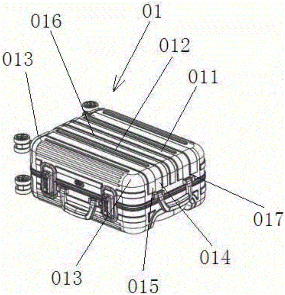
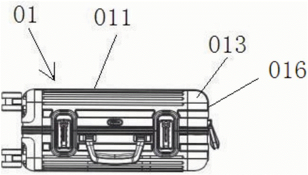
[0015] Attached below figure 1 to attach Figure 4 The present invention is further described.

[0016] refer to Figure 1 to Figure 4 , the stretching process of the arc corner jointing of the metal box shell, including the following steps:

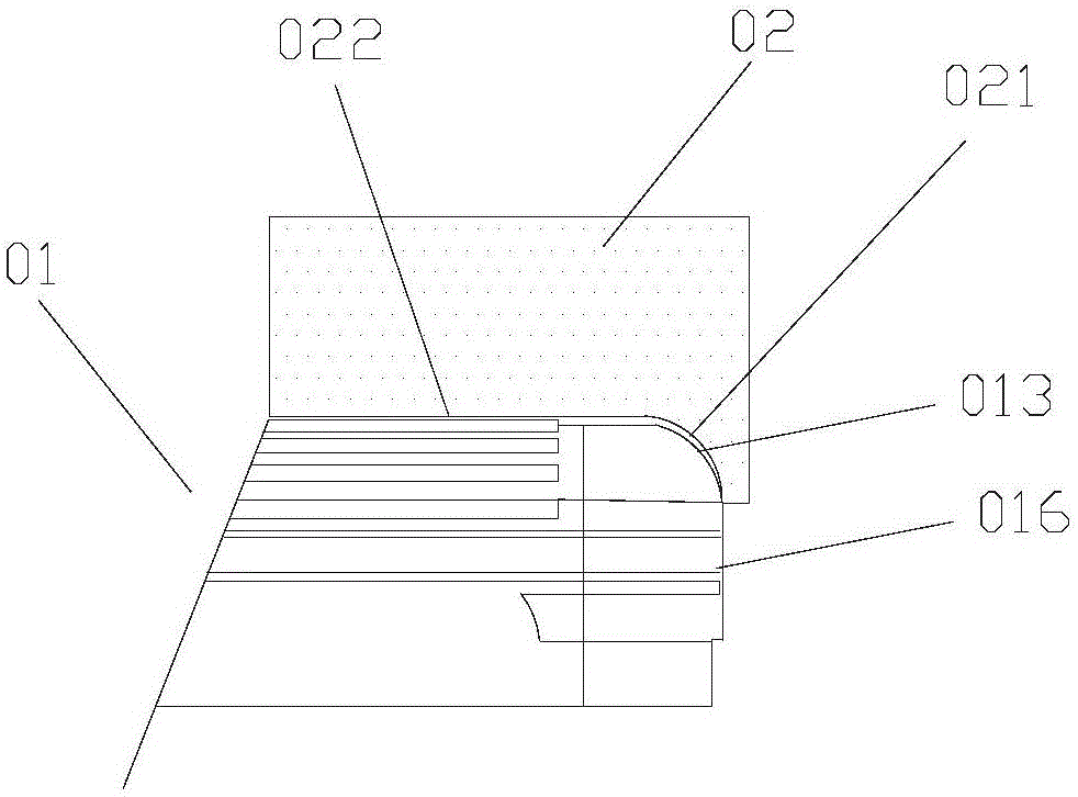
[0017] Prepare the metal rectangular shell 01, the top corner of the metal rectangular shell 01 is the arc corner transition part 013, use the first metal drawing die 02 to stretch the top panel 011 of the metal rectangular shell 01 for the first time, the metal The rectangular shell 01 is copper, copper alloy, aluminum or aluminum alloy shell. Among them, refer to image 3 , the first metal drawing die 02 includes a first arc-shaped groove 021 and a top surface groove 022 connected to the first arc-shaped groove 021, the top panel 011 of the metal rectangular shell 01 is placed at the top surface groove 022, and the side panel A part of 017 is placed at the first arc-shaped groove 021, and the top surface groove 022 is provided wit...


PUM

PropertyMeasurementUnit
Radiusaaaaaaaaaa

Abstract

The invention discloses a drawing process of an arc corner connecting rib of a metal box shell. The drawing process comprises the following steps that the metal rectangular shell is prepared, and arc corner transition portions are arranged at the vertex corners of the metal rectangular shell; a first metal drawing die is used for drawing a top face plate of the metal rectangular shell for the first time, so that a plurality of first convex strips are formed in the first area between the two arc corner transition portions of the top face plate; and a second metal drawing die is used for drawing a side face plate and arc corner transition portions of the metal rectangular shell obtained after first-time drawing molding for the second time, so that a plurality of second convex strips are formed in the second area between the two arc corner transition portions of the side face plate. The drawing process has the beneficial effects that through two times of drawing, arc corners can be orderly, and the stress capacity of the arc corners is improved; meanwhile, convex grain can be formed on the shell, especially on the arc corners, and attractiveness and durability are achieved; especially, die stripping is facilitated in the whole manufacturing process, the production process is simplified, and the occurrence rate of defective goods is lowered.

Description

technical field [0001] The invention belongs to the field of manufacturing metal boxes, and in particular relates to a stretching process for connecting ribs at arc corners of metal box shells. Background technique [0002] Rigid shaped luggage is widely used by people because it can maintain the shape of the appearance and protect the contents of the box to a certain extent, especially the aluminum alloy luggage, which can protect the internal components, with reasonable design and strong structure. Beautiful, easy to use and other characteristics, widely used in instruments, meters, electronics, communications, automation, sensors, precision machinery and other industries, is an ideal box for high-end instruments. Most of the existing boxes and covers are integrally drawn structures, with corrugated grooves or convex lines on the upper and lower surfaces, but there are no boxes with corrugated grooves or convex lines on the sides at the same time. If such a box is stretche...

Claims


Application Information

Patent Timeline
IPC IPC(8): B21D22/20
CPCB21D22/20B21D19/08B21D51/18B21D51/52B21D22/26B32B15/012B32B15/013B21D17/02B21D22/206B21D22/30B21D53/36
Inventor 费晓明
Owner 费晓明
Why Eureka
Eureka Blog
Learn More