Hydraulic punching device

A punching device and hydraulic technology, used in punching tools, metal processing equipment, manufacturing tools, etc., can solve the problems of long cycle and high cost, and achieve the effect of accurate and reliable punching position

Inactive Publication Date: 2015-11-04
SAIC-GM-WULING AUTOMOBILE CO LTD
View PDF6 Cites 2 Cited by
  • Summary
  • Abstract
  • Description
  • Claims
  • Application Information

AI Technical Summary

Problems solved by technology

Hydraulic punching is used instead of traditional stamping die punching, which solves the problem of high cost and long cycle

Method used


Image

  • Hydraulic punching device
  • Hydraulic punching device
  • Hydraulic punching device

Examples


Embodiment Construction

[0025] A hydraulic punching device of the present invention will be further described below in conjunction with the accompanying drawings.

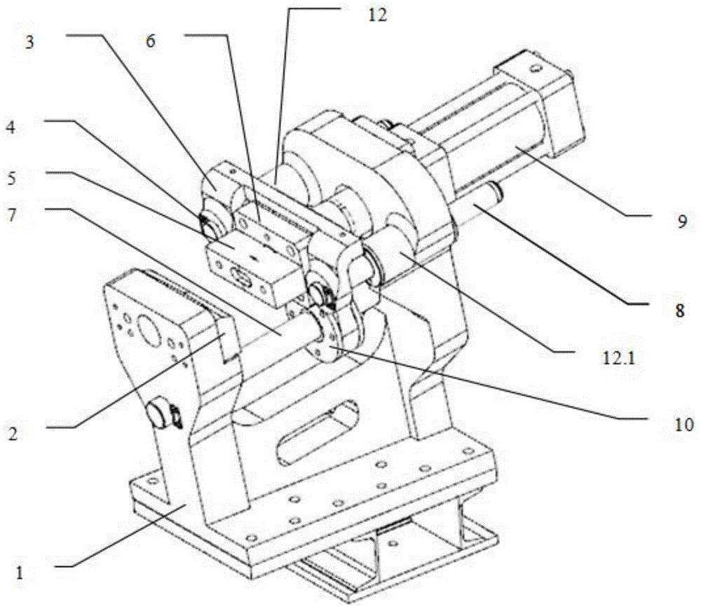
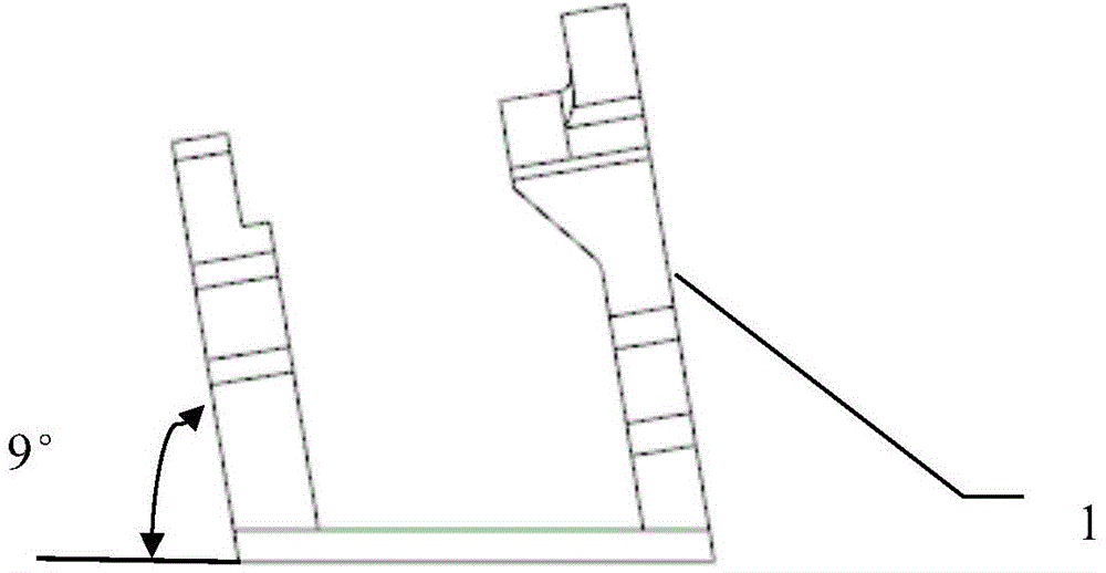
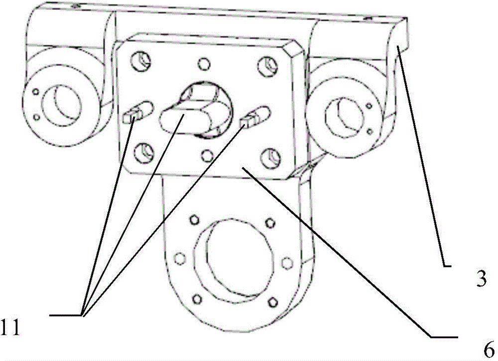
[0026] Such as Figure 1-5 , a hydraulic punching device, including a base 1, a connecting plate 3, a transmission assembly and a hydraulic cylinder 9, the transmission assembly includes a first transmission shaft 4, a second transmission shaft 8 and a third transmission shaft 7 arranged in parallel; the Both the first transmission shaft 4 and the second transmission shaft 8 are slidingly connected to one side of the base 1, and the two ends of the third transmission shaft 7 are respectively fixed on both sides of the base 1; One end of the transmission shaft 4 and the end of the second transmission shaft 8 are respectively fixed with the connecting plate 3, and the connecting plate 3 is slidingly connected with the third transmission shaft 7; the other side of the base 1 is provided with a die 2. There is a depression on the die 2; a st...


PUM


Abstract

The invention discloses a hydraulic punching device. The hydraulic punching device comprises a base, a connection plate, a transmission assembly and a hydraulic cylinder. The transmission assembly comprises a first transmission shaft, a second transmission shaft and a third transmission shaft which are arranged in parallel. The first transmission shaft and the second transmission shaft are both connected with one side of the base in a sliding mode. The two ends of the third transmission shaft are fixed to the two sides of the base respectively. One end of the first transmission shaft and the end of the second transmission shaft are each fixed to the connection plate. The connection plate is connected with the third transmission shaft in a sliding mode. A female die is arranged on the other side of the base. An indented part is formed in the female die. A punching assembly is fixed to the connection plate and comprises a male die, an elastic pressing block and a punch. The elastic pressing block abuts against a part. Transmission is conducted through the three shafts by means of first-stage main guide and second-stage auxiliary guide, deviation of the punch is reduced, and the punching accuracy is ensured. Meanwhile, a traditional punching die is replaced with hydraulic punching, and the problems that cost is high and the period is long are solved.

Description

technical field [0001] The invention relates to the field of punching technology of sheet metal parts, in particular to a hydraulic punching device. technical background [0002] In the field of automobiles, the punching process of sheet metal parts is generally completed in the stamping stage, and when the hole position is changed and increased in the later stage of the automobile sheet metal parts, the general solution is to re-invest the part mold or increase the stamping die equipment of the punching station , not only the input cost is high but also the cycle is long. [0003] If the position of the punching hole is changed or the hole position is added during the production process, there will be no matching mold, and the mold needs to be put into production again. According to the existing technology, it takes half a year to reinvest in a set of punching die equipment worth 800,000 yuan to realize the punching process; at the same time, adding 2 operators will increa...

Claims


Application Information

Patent Timeline
Patent Type & Authority Applications(China)
IPC IPC(8): B21D28/24B21D28/34
Inventor 何冠华张云刘琰
Owner SAIC-GM-WULING AUTOMOBILE CO LTD
Why Eureka
Try Eureka