Micro-electromechanical system (MEMS) triaxial accelerometer and manufacturing method thereof

An axial acceleration and acceleration technology, which is applied in multi-dimensional acceleration measurement, acceleration measurement using inertial force, and fabrication of microstructure devices, etc. The problem of large error, etc., can solve the problem of poor verticality of the three-axis angle, improve the detection sensitivity, and reduce the thermo-mechanical noise.

Active Publication Date: 2012-11-28
SHANGHAI INST OF MICROSYSTEM & INFORMATION TECH CHINESE ACAD OF SCI
View PDF8 Cites 41 Cited by
  • Summary
  • Abstract
  • Description
  • Claims
  • Application Information

AI Technical Summary

Problems solved by technology

The three-axis accelerometer formed by the assembly method will inevitably lead to a large three-axis orthogonality error, large volume, and high cost
In order to realize a single-chip three-axis acceleration sensor, the existing three-axis accelerometer technical solution uses an inertial sensitive mass to realize three-axis acceleration measurement. The disadvantage of this solution is that the acceleration detection of three axes will produce a large deviation Axis sensitivity, and the sensitivity of different axes varies greatly
In order to increase the detection sensitivity, a small capacitive plate gap (such as a few microns) is often required. The compression film damping generated when the capacitive plate moves is very strong, resulting in high thermomechanical noise of the MEMS accelerometer due to air damping, which seriously affects Detection accuracy, so vacuum packaging is required to reduce thermomechanical noise, increasing the difficulty and cost of packaging

Method used


Image

  • Micro-electromechanical system (MEMS) triaxial accelerometer and manufacturing method thereof
  • Micro-electromechanical system (MEMS) triaxial accelerometer and manufacturing method thereof
  • Micro-electromechanical system (MEMS) triaxial accelerometer and manufacturing method thereof

Examples


Embodiment approach

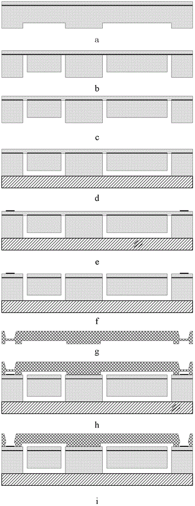
[0048] Reference to the manufacturing method of the variable-area comb-teeth three-axis accelerometer involved in the embodiment of the present invention image 3 The process flow chart shown is described, and the specific process implementation method is as follows:

[0049] As shown in step a, double-sided thermal oxidation, photolithography, and corrosion of the damping cavity are first performed on the SOI sheet.

[0050] As shown in step b, the oxide layer is removed, photolithography, and deep etching using, for example, ICP (Inductively Coupled Plasma) to remove the corresponding part of the SOI substrate silicon under the movable structure.

[0051] As shown in step c, after megasonic cleaning, after removing the sidewall residue generated by ICP etching, for example, BOE (a buffer solution of HF acid) is used to etch the buried oxide layer at the window corresponding to the movable structure.

[0052] As shown in step d, the SOI sheet with a film structure is anodica...


PUM


Abstract

The invention provides a micro-electromechanical system (MEMS) triaxial accelerometer and a manufacturing method thereof. The MEMS triaxial accelerometer comprises a sensitive device layer, an upper cover board layer and a lower supporting body layer, wherein clearances are reserved between the sensitive device layer and the upper cover board layer as well as between the sensitive device layer and the lower supporting body layer; the sensitive device layer comprises a supporting frame body, an elastic beam, three independent sensitive mass blocks, movable comb teeth, fixed comb teeth and an electrode; the three independent sensitive mass blocks in the sensitive device layer are used for detecting acceleration signals of three axes X, Y and Z respectively; an acceleration sensor in each direction is hung in the supporting frame body through the corresponding sensitive mass block by the elastic beam which is only sensitive to the detection direction; a plurality of pairs of movable comb teeth are formed on each sensitive mass block by using a body silicon processing technology; a plurality of pairs of fixed comb teeth are correspondingly formed on the supporting frame body to form a pair of differential capacitors serving as sensitive capacitors; and the differential comb tooth capacitors in different directions generate a differential capacitance change in response to the acceleration signals in the corresponding directions.

Description

technical field [0001] The present invention relates to the field of sensing technology and microelectronic machinery (MEMS) technology. Specifically, the present invention relates to a comb-teeth MEMS three-axis accelerometer, and more specifically to a single-chip variable-area three-axis comb-teeth accelerometer. Sensors and methods of making them. Background technique [0002] Accelerometer is a kind of inertial device, which is widely used in various fields such as automobile, medical treatment, consumer electronics and industry. The three-axis accelerometer after the introduction of MEMS technology has the advantages of small size, light weight, low cross-sensitivity, and mass production. MEMS accelerometers play a huge role in our production and life. At present, they are mainly used in motion perception, action recognition, attitude control, vibration detection, security alarm, etc. Based on accelerometers, more detection functions can be realized and more for a wi...

Claims


Application Information

Patent Timeline
Patent Type & Authority Applications(China)
IPC IPC(8): G01P15/18B81C1/00
Inventor 吴亚明杨丹琼徐静钟少龙
Owner SHANGHAI INST OF MICROSYSTEM & INFORMATION TECH CHINESE ACAD OF SCI
Why Eureka
Try Eureka