Stepwise direct-action piston type high-pressure-difference electromagnetic valve

A high pressure difference, solenoid valve technology, applied in valve details, valve devices, engine components, etc., can solve problems such as the valve core cannot be opened, ordinary solenoid valves cannot be used normally, etc., and achieve the effect of accurate control

Active Publication Date: 2015-11-04
XINGYU ELECTRON (NINGBO) CO LTD
View PDF7 Cites 4 Cited by
  • Summary
  • Abstract
  • Description
  • Claims
  • Application Information

AI Technical Summary

Problems solved by technology

[0003] However, when the solenoid valve is used in a high pressure difference environment, the high pressure difference will cause the valve core to be under pressure and cannot overcome the magnetic force and cannot be opened. Therefore, ordinary solenoid valves cannot be used normally in a high pressure difference environment, and the structure needs to be modified Improvement can meet the needs of use under high pressure

Method used


Image

  • Stepwise direct-action piston type high-pressure-difference electromagnetic valve
  • Stepwise direct-action piston type high-pressure-difference electromagnetic valve
  • Stepwise direct-action piston type high-pressure-difference electromagnetic valve

Examples


Embodiment Construction

[0024] The present invention will be further described in detail below in conjunction with the accompanying drawings and embodiments.

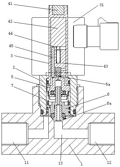
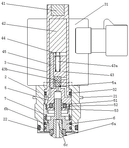
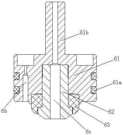
[0025] Such as Figure 1 to Figure 5 Shown is the structural representation of the present invention,

[0026] The reference signs are: valve body 1, air inlet 11, air outlet 12, air passage 13, valve seat 2, rib 21, valve seat sealing ring 22, casing 3, coil 31, casing sealing ring 32. Static iron core 41, first moving iron core 42, second moving iron core 43, spring groove 43a, first valve port gasket 43b, moving iron core spring 44, ejector rod 45, valve nozzle 5, first valve Port 5a, casing 51, valve mouth sealing ring 52, flat gasket 53, valve core assembly 6, second valve port 6a, pilot hole 6b, pressure relief hole 6c, piston rod 61, piston rod sealing ring 61a, valve core guide Column 61b, spool head 62, second valve port sealing gasket 63, spool spring 7.

[0027] Such as Figure 1 to Figure 5 as shown,

[0028] A step-by-step di...


PUM


Abstract

The invention discloses a stepwise direct-action piston type high-pressure-difference electromagnetic valve. The electromagnetic valve comprises a valve body, wherein an air inlet, an air outlet and an air channel communicated with the air inlet and the air outlet are formed in the valve body; a valve holder is assembled on the valve body; a sleeve tube is assembled at the upper end of the valve holder; a coil is arranged at the outer part of the sleeve tube; a static iron core is arranged at the upper end of the sleeve tube; a first movable iron core and a second movable iron core are arranged in the sleeve tube; a movable iron core spring is arranged between the first movable iron core and the second movable iron core; a pushing rod is arranged on the second movable iron core in a penetrating manner; a valve mouth, a valve core assembly and a valve core spring arranged between the valve mouth and the valve core assembly are arranged in the valve holder; a first valve opening is formed in the upper end of the valve mouth; the first valve opening is matched with the lower end of the second movable iron core; a second valve opening is formed in the lower end of the valve core assembly; the second valve opening is matched with the air channel; a pilot hole and a pressure releasing hole are formed in the valve core assembly. The electromagnetic valve has the advantages of being reasonable in structure, and accurate and sensitive to control, and can be suitable for high-pressure-difference environment.

Description

technical field [0001] The invention relates to the technical field of electromagnetic valve manufacturing, in particular to a step-by-step direct-acting piston type high-pressure differential electromagnetic valve. Background technique [0002] A general solenoid valve consists of an excitation coil, a fixed iron core, a compression spring, a movable iron core, and a valve body. Its working principle is that when the excitation coil is not energized, the sealing head of the movable iron core will close the valve under the action of the compression spring and the back pressure of the valve inlet medium. When the excitation coil is energized, the electromagnetic force overcomes the reaction force of the compression spring and the back pressure of the inlet medium of the valve, so that the movable iron core moves to the fixed iron core until the two planes are attracted, and the valve is in the open state. [0003] However, when the solenoid valve is used in a high pressure d...

Claims


Application Information

Patent Timeline
Patent Type & Authority Applications(China)
IPC IPC(8): F16K31/06
CPCF16K31/0644
Inventor 曹建波何金伟龚波明蒋佑华
Owner XINGYU ELECTRON (NINGBO) CO LTD
Why Eureka
Try Eureka