
A solar water heater heat storage unit with a safety device and its installation method

A technology for solar water heaters and safety devices, applied in solar thermal power generation, heating devices, solar thermal devices and other directions, can solve problems such as container damage, potential safety hazards, and equipment heat storage performance degradation, and achieve simple structure, convenient installation, and installation requirements. easy effect

Active Publication Date: 2017-07-25
PIONEER ENERGY JIANGSU
View PDF4 Cites 2 Cited by
  • Summary
  • Abstract
  • Description
  • Claims
  • Application Information

AI Technical Summary

Problems solved by technology

However, these measures can only control the temperature of heat storage medium (phase change material) and heat exchange medium (water), or can only control the pressure of heat exchange medium, and cannot directly control the pressure of heat storage medium (phase change material)
In this way, during long-term use, the pressure in the airtight heat storage unit will inevitably rise gradually, which may cause damage to the container and leakage of the heat storage material, resulting in a decline in the heat storage performance of the equipment and causing safety hazards

Method used


Image

  • A solar water heater heat storage unit with a safety device and its installation method
  • A solar water heater heat storage unit with a safety device and its installation method
  • A solar water heater heat storage unit with a safety device and its installation method

Examples


Embodiment 1

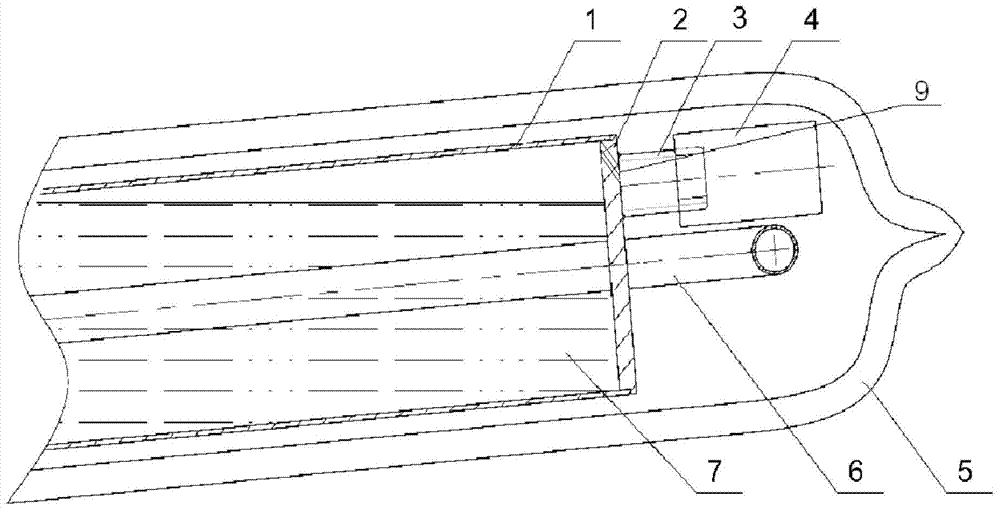
[0027] The heat storage element 1 is a long cylindrical stainless steel container, which contains a certain amount of heat storage material 7 and is provided with U-shaped heat exchange tubes 6 . One end of the cylindrical container is sealed with a flange 2 . The flange 2 is in the shape of an end cap, the maximum outer diameter of which is equal to the outer diameter of the heat storage element, and the smallest outer diameter is slightly smaller than the inner diameter of the heat storage element. There is an inclined pressure relief hole on the outer surface of the flange 2, and the opening of the pressure relief hole inside the flange is located at the top of the smallest outer diameter part. A through-hole stud 3 is welded at the pressure relief hole of the flange, on which a pressure relief valve 4 is installed in a threaded connection. The whole heat storage unit is inserted into the solar vacuum heat collecting tube 5, and the tail of the heat collecting tube is rais...

Embodiment 2

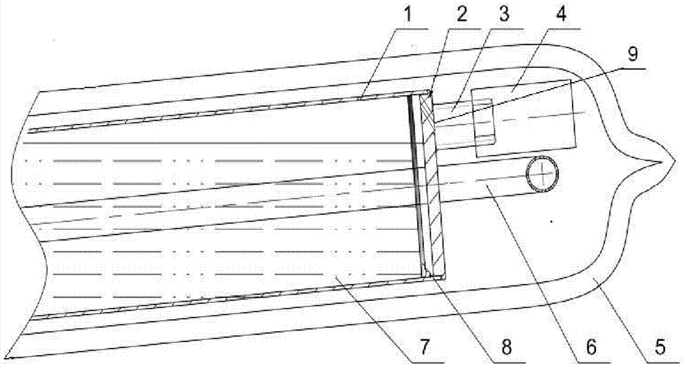
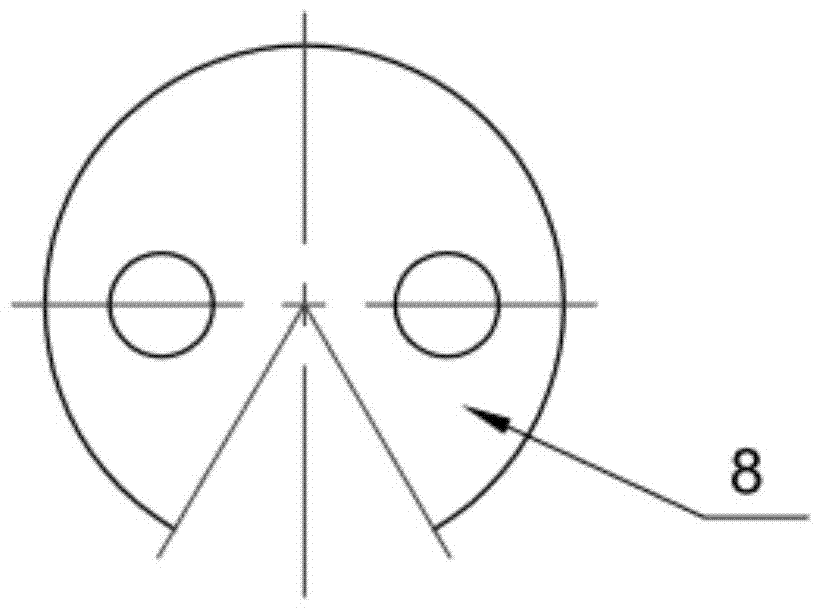
[0029] The heat storage element 1 is a long cylindrical stainless steel container, which contains a certain amount of heat storage material 7 and is provided with U-shaped heat exchange tubes 6 . One end of the cylindrical container is sealed with a flange 2 . The flange 2 is in the shape of an end cap, the maximum outer diameter of which is equal to the outer diameter of the heat storage element, and the smallest outer diameter is slightly smaller than the inner diameter of the heat storage element. An inclined pressure relief hole is formed on the outer surface of the flange, and the opening of the pressure relief hole inside the flange is located at the top of the part with the smallest outer diameter. A metal sheet 8 with a gap is installed near the flange 2. The diameter of the metal sheet 8 is slightly smaller than the inner diameter of the heat storage element, and there is a gap of a certain width with the inner wall of the heat storage element. The gap faces downward ...

Embodiment 3

[0031] The heat storage element 1 is a long cylindrical stainless steel container, which contains a certain amount of heat storage material 7 and is provided with U-shaped heat exchange tubes 6 . One end of the cylindrical container is sealed with a flange 2 . The flange 2 is in the shape of an end cap, the maximum outer diameter of which is equal to the outer diameter of the heat storage element, and the smallest outer diameter is slightly smaller than the inner diameter of the heat storage element. A pressure relief hole perpendicular to the surface is opened on the outer surface of the flange. A U-shaped curved capillary copper tube 8 is welded to the opening of the pressure relief hole inside the flange. The opening of the copper tube 8 is close to the inner wall of the top of the container, and the opening faces and is close to Flange 2 inner surface. A through-hole stud 3 is welded at the pressure relief hole of the flange, on which a pressure relief valve 4 is installe...


PUM


Abstract

The invention relates to a solar water heater heat storage unit with a safety device and an installation method of the heat storage unit. The heat storage unit comprises a heat storage element (1) and a decompression valve (4). A phase-change heat storage material (7) is arranged in the heat storage element (1). A decompression hole (9) is formed in one end of the heat storage element (1), and the decompression valve (4) is fixed to one end of the heat storage element (1) and is communicated with the interior of the heat storage element (1) through the decompression hole (9). The heat storage unit is horizontally or obliquely arranged in a solar collector pipe (5), so that the decompression valve (4) is upward, an opening in the inner side of the decompression hole (9) is higher than the liquid surface of the heat storage material (7). Compared with the prior art, by the adoption of the additionally arranged decompression valve and the simple and convenient installation method, internal pressure of the heat storage unit is limited by releasing gas and a small amount of steam, and safe operation of the heat storage unit is guaranteed. Besides, losses of heat storage mediums are small when the decompression valve is opened, and heat storage capacity of the element is basically not reduced.

Description

technical field [0001] The invention relates to the technical field of solar water heaters, in particular to a heat storage unit of a solar water heater with a safety device and an installation method thereof. Background technique [0002] Phase change heat storage solar water heaters use phase change heat storage materials to store solar energy. Due to the high heat storage density of phase change materials, this type of solar water heater does not require a hot water storage tank, is small in size, easy to install, and has fresh and hygienic water. It is a new type of energy-saving and environmentally friendly product with huge market prospects. Similar to traditional solar water heaters, this type of product also has the problem of high temperature and pressure of the heat storage medium caused by the environment and use, especially when the house has not been delivered or is unoccupied for a long time, there is no tap water source, and the water heater is empty. conditi...

Claims


Application Information

Patent Timeline
Patent Type & Authority Patents(China)
IPC IPC(8): F24J2/46F24J2/34
CPCY02E10/40
Inventor 郑辉张继皇陈良黄剑进王鋐
Owner PIONEER ENERGY JIANGSU
Learn More