
Detecting radar blockage based on drive history

A detection system and predetermined value technology, applied in the direction of measuring devices, radio wave measurement systems, instruments, etc., can solve problems such as echo attenuation

Inactive Publication Date: 2015-11-04
FORD GLOBAL TECH LLC
View PDF4 Cites 9 Cited by
  • Summary
  • Abstract
  • Description
  • Claims
  • Application Information

AI Technical Summary

Problems solved by technology

Under these conditions, the echo may be attenuated so that low radar echo signals are measured

Method used


Image

  • Detecting radar blockage based on drive history
  • Detecting radar blockage based on drive history
  • Detecting radar blockage based on drive history

Examples


Embodiment Construction

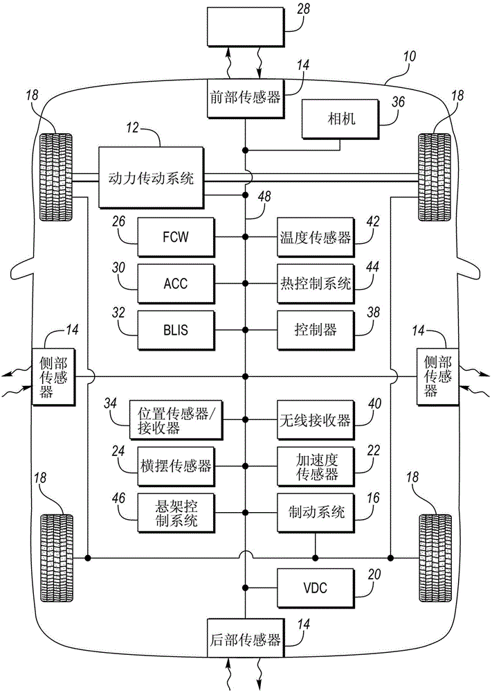
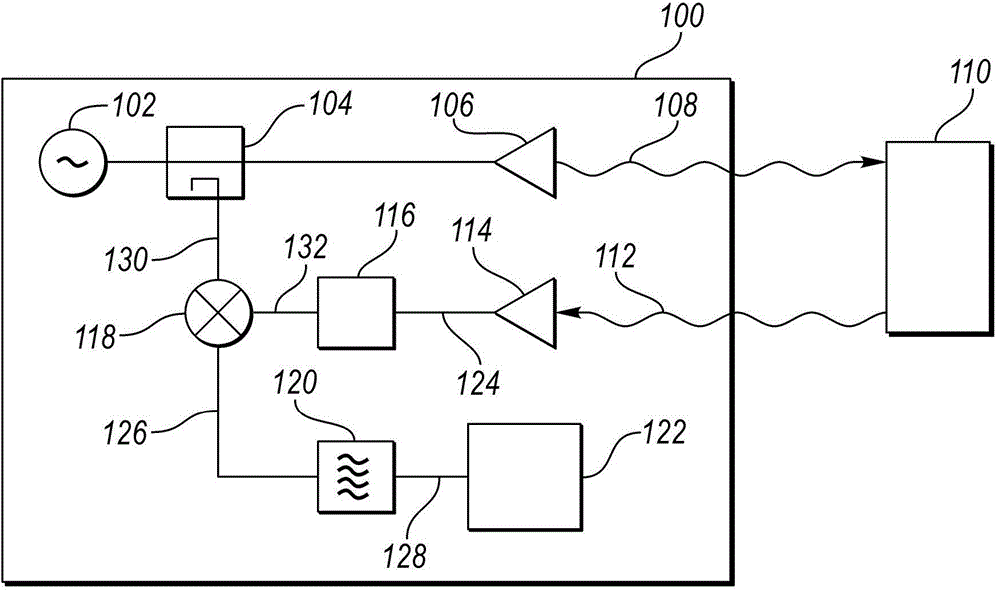
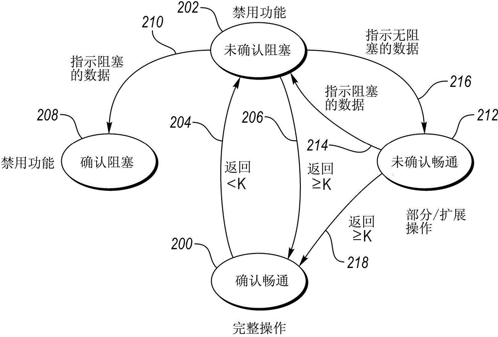
[0013] Embodiments of the present disclosure are described herein. It should be understood, however, that the disclosed embodiments are merely examples and that other embodiments may utilize various alternatives. The figures are not necessarily to scale; some features may be exaggerated or minimized to show details of particular components. Therefore, specific structural and functional details disclosed herein are not to be interpreted as limiting, but merely as a representative basis for teaching one skilled in the art to variously employ the present invention. As will be understood by persons of ordinary skill in the art, various features illustrated and described with reference to any one figure may be combined with features illustrated in one or more other figures to form embodiments not explicitly illustrated or described. Combinations of features described provide representative embodiments for typical applications. However, various combinations and modifications of th...


PUM


Abstract

A vehicle includes a radar sensor for detecting objects in the vehicle path. The radar sensor may become blocked by contaminants or debris. A controller monitoring the radar system may detect a radar blockage when a return signal magnitude is less than a threshold. A typical response may be to set a radar blockage diagnostic under such a condition. The controller may inhibit setting a radar blockage diagnostic when other data indicates that the radar sensor is not blocked. Data such as vehicle position, traffic information, camera images, and historical radar returns may be used. A controller may confirm a radar blockage diagnostic when other data indicates that the radar sensor may be blocked. Data such as temperature, vehicle position, surface roughness, automated brake interventions, and heating system status may be used. Return signal dependent functions may be operated based on the radar blockage diagnostic.

Description

technical field [0001] The present application relates generally to motor vehicle radar system diagnostics. Background technique [0002] Vehicles may include sensors for detecting objects around the vehicle. The sensor may be a radar system that emits electromagnetic waves and receives reflected signals from targets. The relative speed and distance of the target can be detected based on the characteristics of the echo signal. To operate properly, radar must be able to transmit and receive electromagnetic signals. In some cases, the transmitted signal and the received signal may be attenuated. Debris or obstacles in front of the radar unit can cause attenuation of the radar signal. For example, mud, ice or snow in front of the radar unit may impede radar function. Under these conditions, the echo may be attenuated such that low radar echo signals are measured. The radar diagnostic system may diagnose a radar fault condition and disable operation of radar-related functi...

Claims


Application Information

Patent Timeline
IPC IPC(8): G01S7/40G01S13/931
CPCG01S13/02G01S7/4026G01S13/931G01S13/867G01S2013/93274G01S2013/93272G01S2013/9322G01S2013/932G01S2013/9316G01S2013/93271G01S7/4039B60K31/00B60W50/029
Inventor 夏恩·埃尔沃特亚伦·米尔斯多瑞恩·杰克·斯派洛
Owner FORD GLOBAL TECH LLC
Learn More