
Air measurement type antenna device

An antenna device and air measurement technology, applied in the direction of the structure connection of the antenna grounding switch and the structure of the radiating element, can solve the problems of affecting the performance of the antenna, increasing the surface wave of the antenna, and high processing costs, achieving accurate measurement accuracy and improving the axial ratio. Good bandwidth and antenna performance

Inactive Publication Date: 2015-11-04
GUANGZHOU HI TARGET NAVIGATION TECH
View PDF6 Cites 10 Cited by
  • Summary
  • Abstract
  • Description
  • Claims
  • Application Information

AI Technical Summary

Problems solved by technology

However, the increase of the surface wave on the surface of the antenna will affect the performance of the antenna; at the same time, the weight and cost of the product will increase accordingly; and if the single-layer dielectric increases to more than 7mm, the processing will be difficult and the processing cost will be high, which will also cause product defect rate. Increase

Method used


Image

  • Air measurement type antenna device
  • Air measurement type antenna device
  • Air measurement type antenna device

Examples


Embodiment Construction

[0020] In order to facilitate the understanding of the present invention, the present invention will be described more fully below with reference to the associated drawings. Preferred embodiments of the invention are shown in the accompanying drawings. However, the present invention can be embodied in many different forms and is not limited to the embodiments described herein. On the contrary, these embodiments are provided to make the understanding of the disclosure of the present invention more thorough and comprehensive.

[0021] It should be noted that when an element is referred to as being “fixed” to another element, it can be directly on the other element or there can also be an intervening element. When an element is referred to as being "connected to" another element, it can be directly connected to the other element or intervening elements may also be present.

[0022] Unless otherwise defined, all technical and scientific terms used herein have the same meaning as...


PUM


Abstract

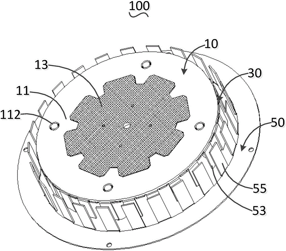
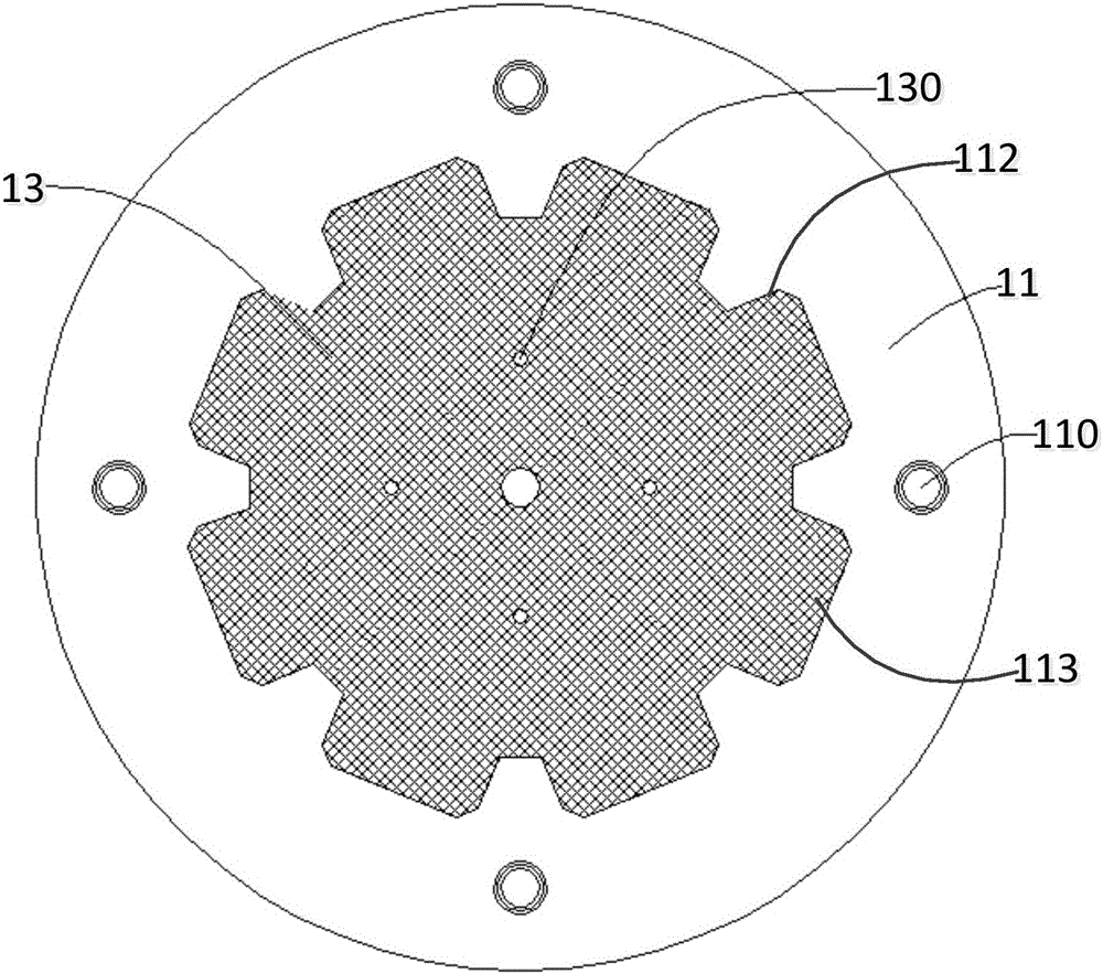
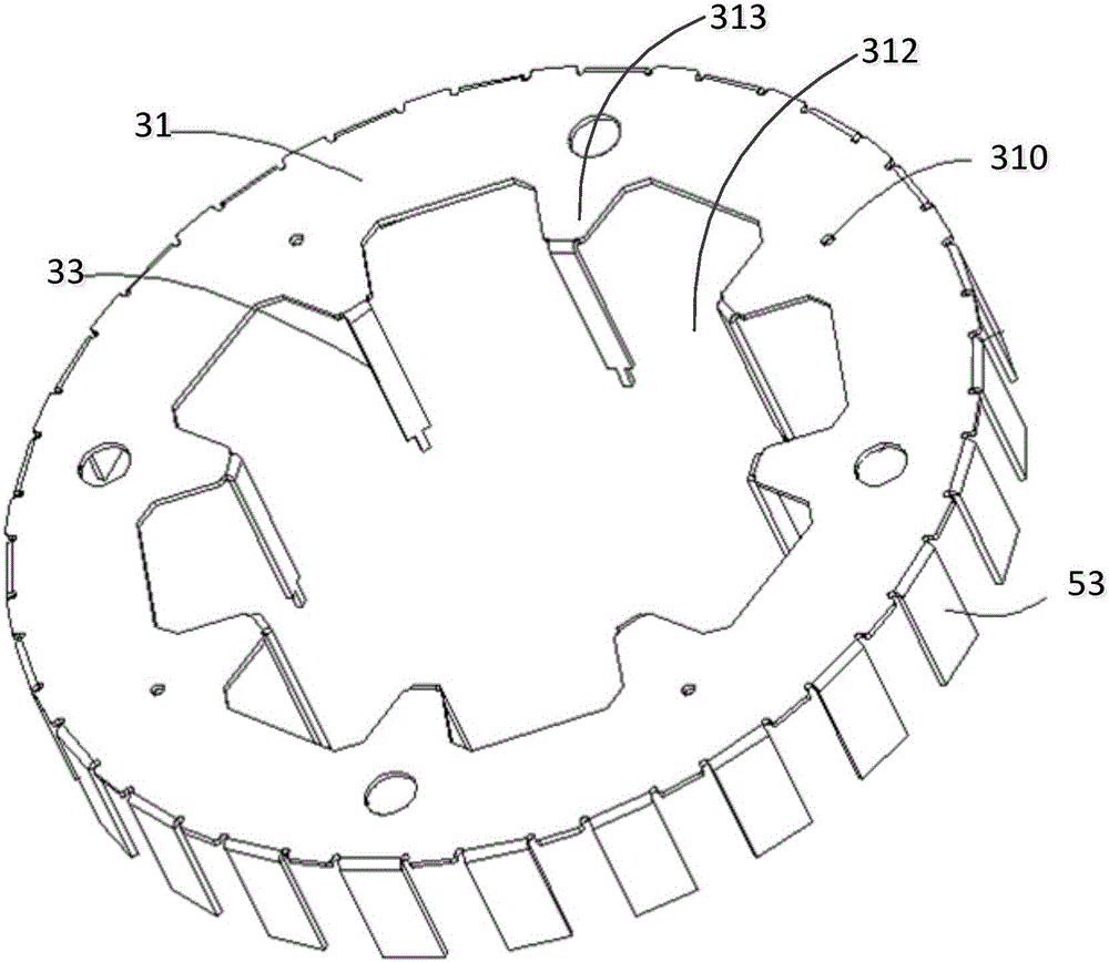
The invention relates to an air measurement type antenna device, which comprises a first signal receiving unit, a second signal receiving unit, a circuit board and a tuning unit, wherein the first signal receiving unit comprises a substrate and a microstrip patch layer, the second signal receiving unit comprises a metal piece and a grounding piece, the metal piece is connected with the circuit board through the grounding piece, the substrate is arranged on the metal piece, and the microstrip patch layer is arranged on the substrate and shares an air radiation medium layer with the metal piece; and the tuning unit comprises a fixed plate, first tuning sawteeth and a plurality of second tuning sawteeth; the fixed plate is arranged on the circuit board, the first tuning sawteeth are uniformly arranged on the metal piece, and the second tuning sawteeth are in one-to-one correspondence relation with the first tuning sawteeth. According to the invention, the first tuning sawteeth and the second tuning sawteeth are arranged in a one-to-one correspondence mode, so that the first tuning sawteeth and the second tuning sawteeth are arranged as many as possible in the limited area, thereby well improving performance parameters such as the axis ratio bandwidth, the beam bandwidth, low-elevation radiation gain and the like while realizing a miniaturized structure.

Description

technical field [0001] The invention relates to the technical field of antennas, in particular to an air measuring antenna device. Background technique [0002] Due to the narrow bandwidth of the traditional microstrip antenna, especially when the medium with a low dielectric constant is used as the antenna substrate material, the gain at low elevation angles is low, resulting in poor performance of the antenna for receiving satellite signals at low angles; although the medium with a high dielectric constant can improve the beam bandwidth, but will result in a narrower bandwidth of the antenna. In this way, it is necessary to adopt a double-layer structure or a multi-layer structure to realize good reception of dual-band L1 (1521MHz-1620MHz) and L2 (1160MHz-1300MHz) satellite signals of the antenna. However, the traditional stacked dual-frequency antenna device is difficult to realize the structure design of the light and small antenna, and the cost is relatively high. [...

Claims


Application Information

Patent Timeline
Patent Type & Authority Applications(China)
IPC IPC(8): H01Q1/38H01Q1/36H01Q1/50
CPCH01Q1/38
Inventor 李晓鹏李庚禄邓良友张华福黄建忠
Owner GUANGZHOU HI TARGET NAVIGATION TECH
Learn More