
Intelligent driving type self-rotation electric-control screw

A technology of driving and rotating motors, applied in metal processing, metal processing equipment, manufacturing tools, etc., can solve problems such as difficulties, inconvenient, and difficult inspection by operators, so as to ensure work efficiency, strong work performance, and improve work efficiency Effect

Inactive Publication Date: 2015-11-11
SUZHOU XUANHE IOT TECH
View PDF11 Cites 6 Cited by
  • Summary
  • Abstract
  • Description
  • Claims
  • Application Information

AI Technical Summary

Problems solved by technology

[0005] It can be seen from the screws of the prior art that the designer put forward many useful improvement suggestions in order to make the screw have a more stable structure and a more reliable fixing effect. However, from the actual use of the screw, the existing screw There are still some unavoidable problems. For example, in some narrow spaces, it is very inconvenient to apply screws. Whether it is to align the screw holes to place the screws or to twist the screws for installation, it is very inconvenient; not only that, As time goes by, some screws are prone to loosening, which will affect the stability of the workpieces they are installed on, which requires staff to check at all times. On the one hand, more manpower needs to be arranged. Not only is it difficult for the operator to check the space, but it is also very difficult to rotate and install again.

Method used


Image

  • Intelligent driving type self-rotation electric-control screw
  • Intelligent driving type self-rotation electric-control screw

Examples


Embodiment Construction

[0022] The specific implementation manners of the present invention will be further described in detail below in conjunction with the accompanying drawings.

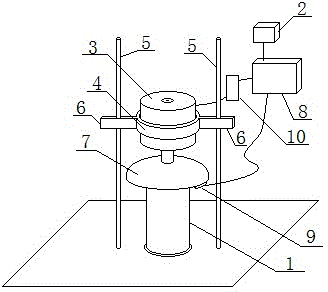
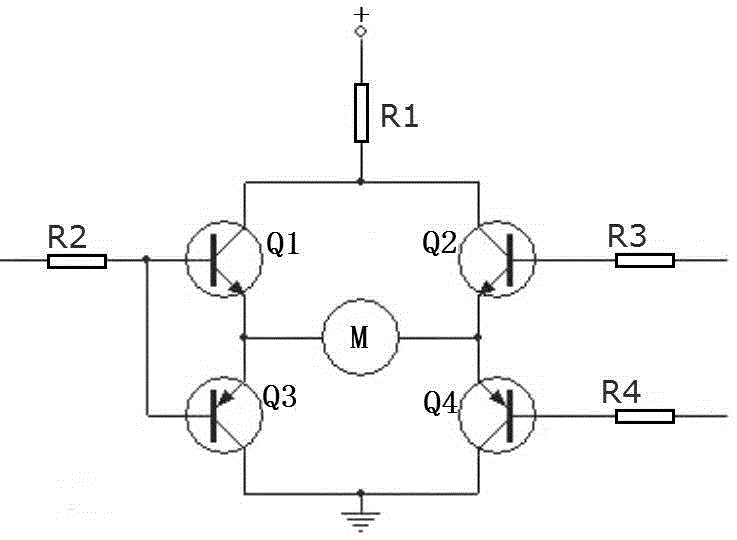
[0023] Such as figure 1As shown, an intelligently driven self-rotating electric control screw designed by the present invention includes a screw body 1 and a screw cap 7 fixedly arranged on the top of the screw body 1; it also includes a fixed snap ring 4, a rotating motor 3, at least one Positioning rod 5, a control module 8, and external power supply module 2, ranging sensor 9, motor drive circuit 10 connected with control module 8 respectively; Rotating motor 3 is connected with control module 8 through motor drive circuit 10; Wherein, external The power supply module 2 supplies power to the distance measuring sensor 9 through the control module 8, and at the same time, the external power supply module 2 supplies power to the rotating motor 3 through the control module 8 and the motor drive circuit 10 in turn; the dr...


PUM


Abstract

The invention relates to an intelligent driving type self-rotation electric-control screw. The intelligent driving type self-rotation electric-control screw comprises a screw body (1), a screw cap (7) fixedly arranged at the top end of the screw body (1), a fixing clamping ring (4), a rotary motor (3), at least one positioning rod (5), a control module (8), an externally connected power source module (2), a distance measuring sensor (9) and a motor driving circuit (10), wherein the externally connected power source module (2), the distance measuring sensor (9) and the motor driving circuit (10) are connected with the control module (8). Based on the technical scheme of the design of the intelligent driving type self-rotation electric-control screw, all the parts are connected and installed to form the intelligent driving type self-rotation electric-control screw. The intelligent driving type self-rotation electric-control screw is modified based on an existing screw structure, an electric control structure is designed, the rotary motor (3) is introduced, and self-rotation of the rotary motor (3) is overcome by cooperatively designing the positioning rods (5). Therefore, self-rotation installation operation and real-time detection self-screwing operation of the screw are realized, the condition of narrow installation space and a looseness phenomenon can be effectively handled, and the work efficiency in the actual application is greatly improved.

Description

technical field [0001] The invention relates to an intelligently driven self-rotating electric control screw, which belongs to the technical field of intelligent hardware. Background technique [0002] A screw is a tool that uses the physical and mathematical principles of the oblique circular rotation and friction of the object to tighten the workpiece step by step; screws are indispensable industrial necessities in daily life: such as cameras, glasses, clocks, electronics, etc. General screws for televisions, electrical products, musical instruments, furniture, etc.; large screws and nuts for engineering, construction, and bridges; large and small screws for transportation equipment, airplanes, trams, and automobiles; Industry has important tasks. As long as there is industry on the earth, the function of screws will always be important. Screws are a common invention in people's production and life for thousands of years. According to the application field, it is the large...

Claims


Application Information

Patent Timeline
Patent Type & Authority Applications(China)
IPC IPC(8): B23P19/06
CPCB23P19/06
Inventor 张瑜陈黛文李进荣
Owner SUZHOU XUANHE IOT TECH
Learn More