

Bottle lifting device for filling machine
A lifting device and filling machine technology, applied in liquid bottling, packaging, bottle filling, etc., can solve problems such as poor sealing of the lifting device, air leakage affecting the life of seals, and bottle mouth leakage, so as to improve filling efficiency The effect of filling accuracy, prolonging service life and simple structure
- Summary
- Abstract
- Description
- Claims
- Application Information
AI Technical Summary
Problems solved by technology
Method used
Image

Examples
Embodiment Construction
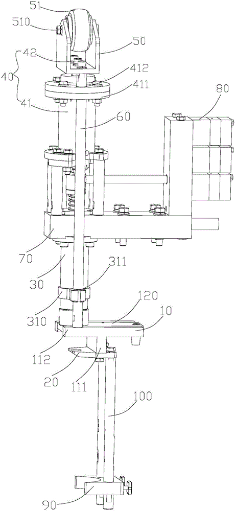
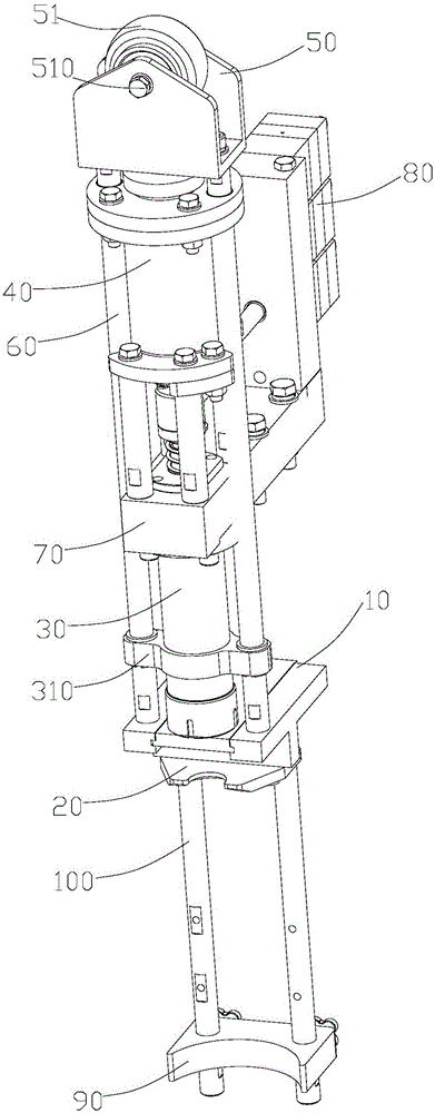
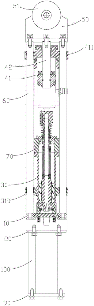
[0023] Such as figure 1 , 2 As shown, a bottle lifting device of a filling machine includes a dummy cup 10, a bottle clamping plate 20, and a cylinder 40 arranged above the filling valve 30. The telescoping part of the cylinder 40 is provided with a roller seat 50. Roller seat 50 is provided with roller 51, and the both sides of described roller seat 50 is provided with guide bar 60 respectively, and the end of described guide bar 60 away from roller seat 50 is connected with described dummy cup 10, and the bottom of described dummy cup 10 The end is connected with the bottle clamping plate 20, the dummy cup 10 is located below the valve port of the filling valve 30, and the axis line of the cylinder 40, the axis line of the filling valve 30 and the longitudinal center line of the roller 51 coincide. The cylinder 40 includes a cylinder seat 41, a piston rod 42 arranged in the cylinder seat 41, and the bottle lifting device of the filling machine also includes a connection se...
PUM
 Abstract
Description
Claims
Application Information