Levered protective window for use in building construction
A construction and lever-type technology, applied in the field of protective windows, can solve problems such as waste, labor-intensive, and complicated procedures, and achieve the effect of convenient installation and strong practicability
- Summary
- Abstract
- Description
- Claims
- Application Information
AI Technical Summary
Problems solved by technology
Method used
Image
Examples
Embodiment 1
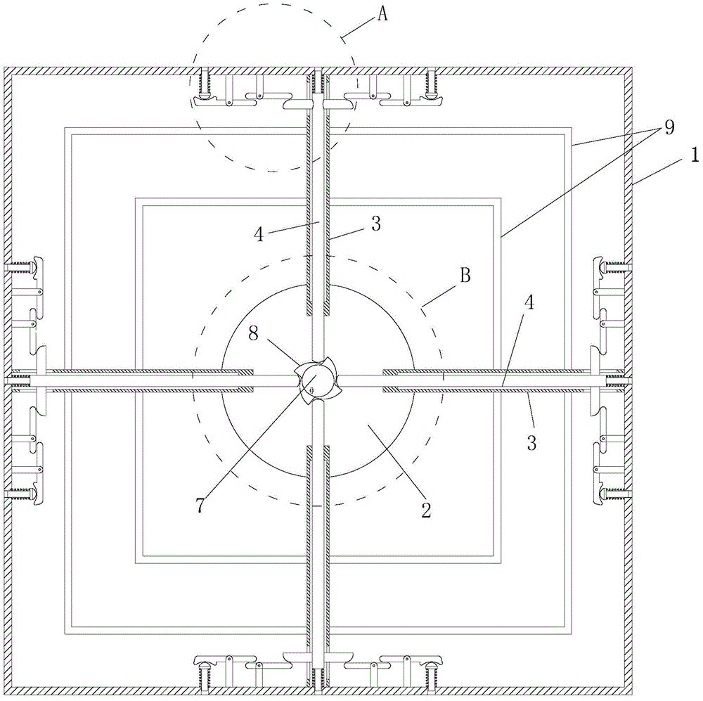
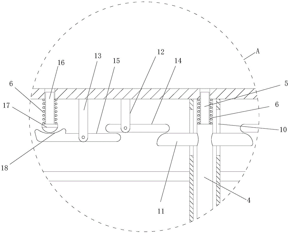
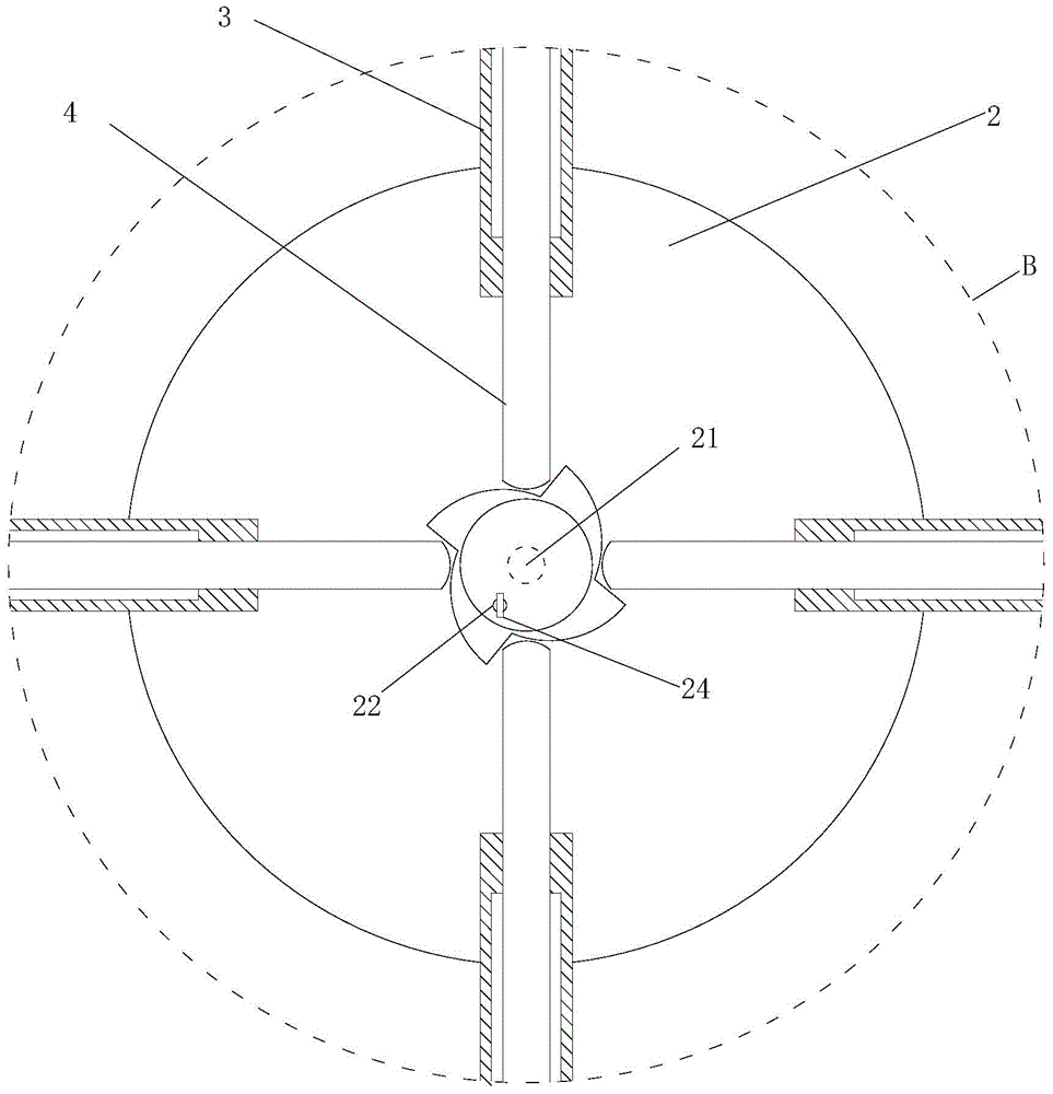
[0027] Such as figure 1 , 2 , 3, the lever-type protective window used in the building construction described in this embodiment includes a square outer frame 1, a chassis 2 is provided at the center of the outer frame 1, and a chassis 2 is provided between the outer frame 1 and the chassis 2. Four pipe bodies 3 that are generally distributed in a cross shape are provided with telescopic rods 4 inside the pipe bodies 3. The outer ends of the telescopic rods 4 are diameter-reducing sections 5 that can extend out of the outer frame 1 and are on the diameter-reducing section 5. A spring 6 is provided, and the inner end of the telescopic rod 4 is an arc-shaped head that exposes the pipe body 3. The center of the chassis 2 is provided with a rotatable and lockable cam 7, and the circumference of the cam 7 is provided with four cams at 90 degrees. The blades 8 that are distributed at intervals and whose width gradually increases, when the cam 7 rotates, the blades 8 can push out th...
Embodiment 2
[0034] Such as Figure 7 , 8 , 9, and 10, the lever-type protective window used in the building construction described in this embodiment is different from Embodiment 1 in that: four corners of the outer frame 1 and the chassis 2 are provided with four oblique connections Plate 25, the protective strip 9 is connected between the inclined connecting plate 25 and the pipe body 3, the end of the inclined connecting plate 25 close to the top corner is provided with a chute 26, and an L-shaped block 27 is arranged above the chute 26 , the horizontal side of the L-shaped block 27 is parallel to the horizontal side of the outer frame 1, the vertical side of the L-shaped block 27 is parallel to the vertical side of the outer frame 1, and a slide block 28 is provided at the bottom of the L-shaped block 27 corners, The slider 28 is arranged in the chute 26, the slider 28 can move in the chute 26 and be limited by the chute 26, between the horizontal edge of the L-shaped block 27 and th...
PUM
 Abstract
Description
Claims
Application Information
 - R&D
- Intellectual Property
- Life Sciences
- Materials
- Tech Scout
- Unparalleled Data Quality
- Higher Quality Content
- 60% Fewer Hallucinations
Browse by: Latest US Patents, China's latest patents, Technical Efficacy Thesaurus, Application Domain, Technology Topic, Popular Technical Reports.
© 2025 PatSnap. All rights reserved.Legal|Privacy policy|Modern Slavery Act Transparency Statement|Sitemap|About US| Contact US: help@patsnap.com


