Double-valve-element electronic thermostat based on vehicle type carrying hydrodynamic retarder

A technology of hydraulic retarder and thermostat, which is applied in machine/engine, engine cooling, coolant flow control and other directions, can solve problems such as large error, wear and shorten the use time of retarder.

Inactive Publication Date: 2015-11-11
SHAANXI FAST GEAR CO
View PDF6 Cites 8 Cited by
  • Summary
  • Abstract
  • Description
  • Claims
  • Application Information

AI Technical Summary

Problems solved by technology

[0004] Due to the limitations of the structure of the wax-type thermostat, when it changes with the temperature of the coolant, the execution of the thermostat is slow, and the cooling intensity cannot be changed in time according to the working temperature of the vehicle cooling system, so there are slow response and lag time Shortcomings such as long length, large error, and low control accuracy make the engine unable to work at the optimum operating temperature, and high and low temperatures will occur, resulting in serious heat transfer loss and wear of the engine, increased fuel consumption rate, and increased harmful emissions; It also makes the main valve of the thermostat unable to open quickly when the hydraulic retarder is working, and the cooling system of the whole vehicle cannot go through a large cycle in time, and is not in the best cooling state, resulting in the heat generated by the hydraulic retarder. The coolant is taken away, which shortens the use time of the retarder and reduces the efficiency of the retarder

Method used


Image

  • Double-valve-element electronic thermostat based on vehicle type carrying hydrodynamic retarder
  • Double-valve-element electronic thermostat based on vehicle type carrying hydrodynamic retarder
  • Double-valve-element electronic thermostat based on vehicle type carrying hydrodynamic retarder

Examples


Embodiment Construction

[0024] The present invention will be further described in detail below in conjunction with the accompanying drawings.

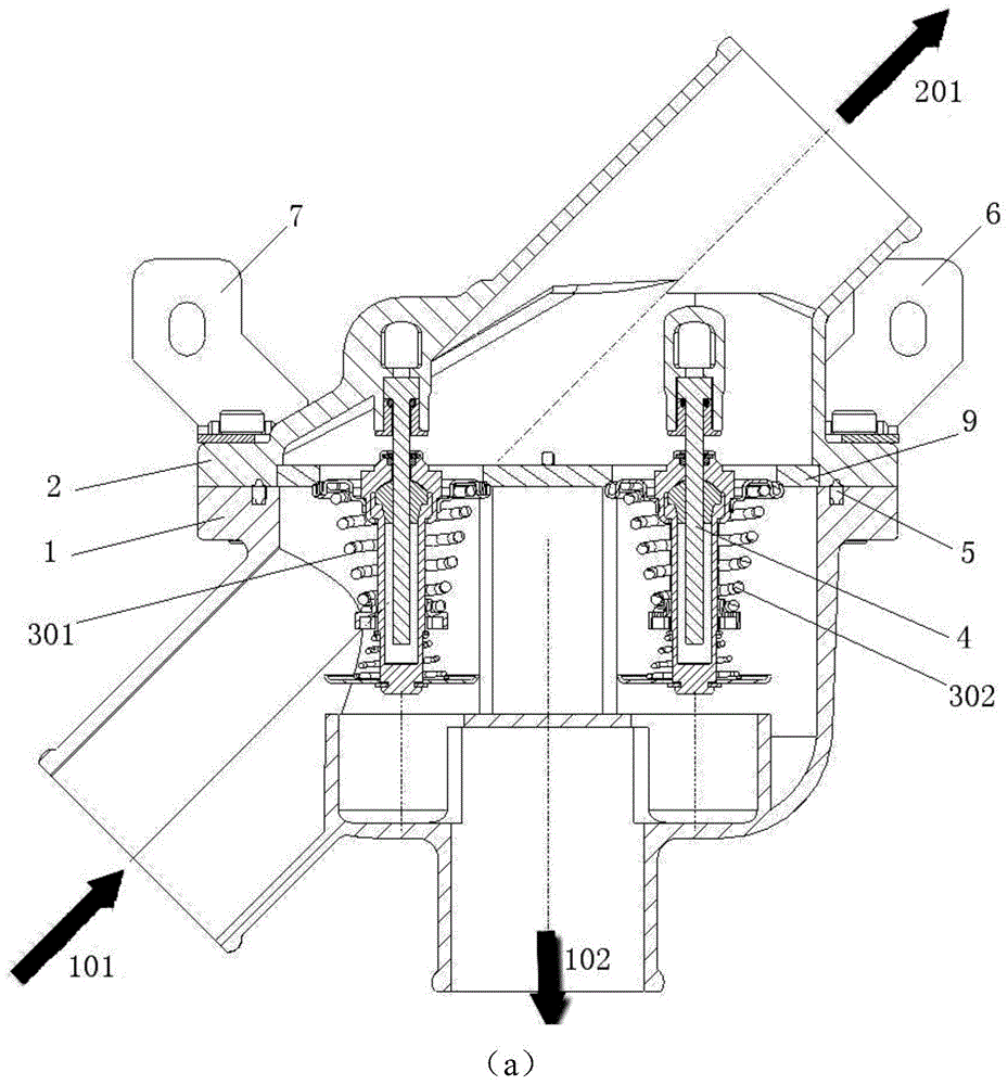
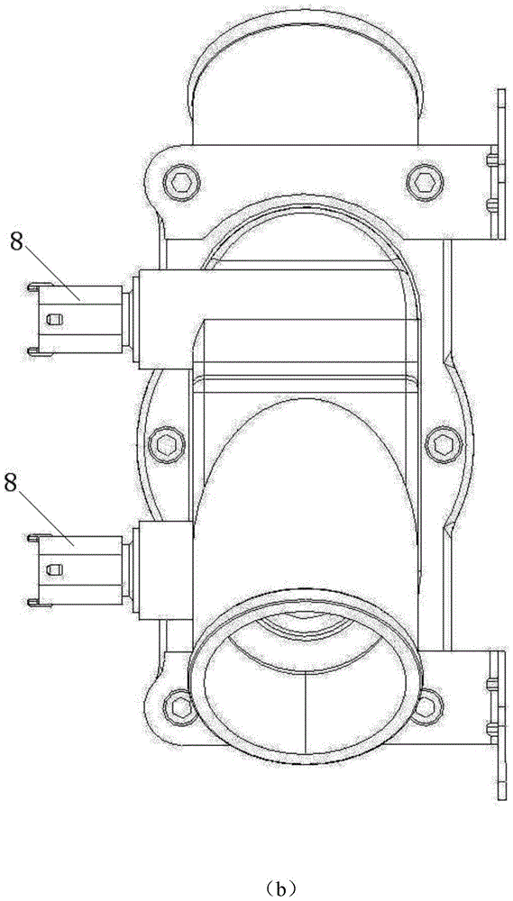
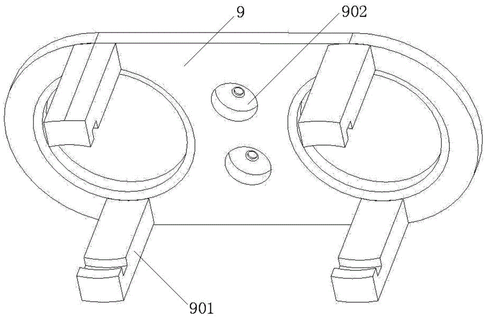
[0025] like Figure 1 to Figure 3 As shown, the present invention is a dual-spool electronic thermostat based on a vehicle equipped with a hydraulic retarder, which includes a supporting base 1 and an upper cover 2, and an internal cavity is formed between the base 1 and the upper cover 2 , and the base 1 is provided with a water inlet 101 connected to the retarder coolant outlet, the small circulation outlet 102 is connected to the water pump inlet, and the upper cover 2 is provided with a large circulation outlet 201 connected to the vehicle radiator, and through the vehicle radiator It is connected to the water inlet of the water pump, and the water outlet of the water pump is connected to the coolant inlet of the retarder; a transition plate 9 is provided between the base 1 and the upper cover plate 2, and the large circulation outlet of the first thermos...


PUM


Abstract

The invention discloses a double-valve-element electronic thermostat based on a vehicle type carrying a hydrodynamic retarder. The double-valve-element electronic thermostat comprises a base and an upper cover plate. The base and the upper cover late are used in cooperation, and an inner cavity is formed between the base and the upper cover plate. A water inlet and a small circulation water outlet are formed in the base, and a large circulation water outlet is formed in the upper cover plate. A transition plate is arranged between the base and the upper cover plate. A large circulation outlet of a first thermostat core and a large circulation outlet of a second thermostat core are formed in the transition plate. One ends of two electronic heaters are fixed to the upper cover plate and led out of the upper cover plate through electric connectors, and the other ends of the two electronic heaters manner the large circulation outlet of the first thermostat core and the large circulation outlet of the second thermostat core respectively and are provided with the first thermostat core and the second thermostat core respectively. A small circulation outlet of the first thermostat core and a small circulation outlet of the second thermostat core are formed in the corresponding positions in the base and communicated with the small circulation water outlet.

Description

Technical field: [0001] The invention relates to an electronic thermostat, in particular to a double-spool electronic thermostat based on a vehicle equipped with a hydraulic retarder. Background technique: [0002] The function of the thermostat in the vehicle cooling system is to automatically adjust the opening of the valve according to the temperature of the coolant to change the large and small circulation process of the cooling system, adjust the amount of flow into the radiator, and finally realize the adjustment of the vehicle cooling system. Heat dissipation capacity, that is, cooling intensity. At present, the wax-type thermostat is widely used in the vehicle cooling system. Its working principle is to use the volume expansion of solid paraffin heated and melted to control the opening of the thermostat valve, and then control the flow direction and flow of the coolant to realize the cooling intensity. adjust. [0003] With the widespread use of hydraulic retarders...

Claims


Application Information

Patent Timeline
Patent Type & Authority Applications(China)
IPC IPC(8): F01P7/16
Inventor 高帅吴鹏史波峰
Owner SHAANXI FAST GEAR CO
Why Eureka
Try Eureka