safety shut-off valve

A safety shut-off valve and valve body technology, applied in the direction of lift valve, valve device, engine components, etc., can solve the problems of difficult maintenance, large pressure loss, and the requirement of increasing closing force, so as to increase the safety performance and facilitate maintenance. Maintenance, the effect of reducing pressure loss

Active Publication Date: 2017-10-31
TERRENCE ENERGY
View PDF8 Cites 0 Cited by
  • Summary
  • Abstract
  • Description
  • Claims
  • Application Information

AI Technical Summary

Problems solved by technology

[0003] The application number is CN20141008170.4 Chinese patent proposes an axial-flow safety cut-off valve. The reset handwheel adopts an axial structure. Regardless of reset or cut-off, the cylindrical gear is always in contact, which will cause wear between the teeth in the area, and at the same time , during the cutting process, there will be friction between the gears, which increases the requirements for the closing force, resulting in a reset force during the operation. During maintenance, it cannot be disassembled as an independent whole. It needs to be disassembled by parts, which increases the difficulty of maintenance. ; In addition, in this design, the uniaxial and lever method is adopted. This design has high requirements on the performance of the lever, which increases the difficulty of manufacturing and relatively high cost requirements
[0004] The application number is CN201410409894.X Chinese patent proposes another safety cut-off valve. This structure is an eccentric reset method, which requires high performance requirements for the cut-off screw and threaded connection. This structure does not have a labor-saving structure. In the design of the flow channel, there is a tortuous channel inside, which will produce a large pressure loss compared with the cut-off valve with a similar straight pipe section. At the same time, the structure adopts a segmented design, and the leakage is relatively small. Many, more difficult to maintain

Method used


Image

  • safety shut-off valve
  • safety shut-off valve
  • safety shut-off valve

Examples


Embodiment Construction

[0030] The safety cut-off valve of the present invention will be further described below in conjunction with the accompanying drawings and specific embodiments, but it is not intended to limit the present invention.

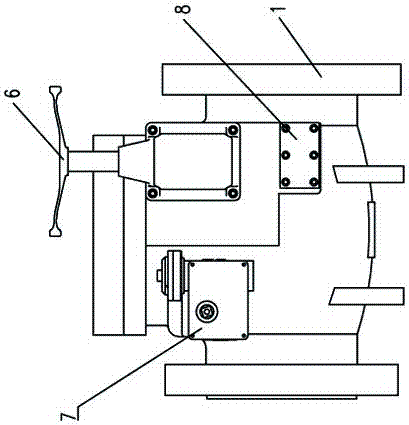
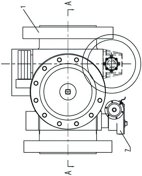
[0031] Such as Figure 2-4 As shown, the safety cut-off valve in a specific embodiment of the present invention includes a valve body 1, an upper cover plate 5, a cutting member, a handwheel assembly 6 and an actuator 7, and the upper cover plate 5 is installed on the upper end of the valve body 1, and the upper cover The plate 5 and the valve body 1 are sealed by an O-ring. The valve body 1 is provided with a flow channel. The handwheel assembly 6 is connected to the main shaft assembly 3 in the cut-off part. When the pressure is abnormal, the cut-off part cuts off the flow in the valve body 1. Channel; wherein, the cut-off component includes a valve plate assembly 2, a main shaft assembly 3 and a reset shaft assembly 4, the main shaft assembly 3 and the reset s...


PUM


Abstract

The invention provides a safety shut-off valve which comprises a valve body, an upper cover plate, a shut-off component and a hand wheel assembly. A circulation channel is arranged in the valve body. The hand wheel assembly is connected with the shut-off component. The hand wheel assembly drives the shut-off component to shut off the circulation channel in the valve body when the pressure is abnormal. The shut-off component comprises a valve plate assembly, a main shaft assembly and a reset shaft assembly. The main shaft assembly and the reset shaft assembly are arranged on the valve body in parallel. One end of the valve plate assembly is connected with the main shaft assembly. The valve plate assembly can rotate relative to the main shaft assembly. The main shaft assembly is connected with the hand wheel assembly. When the safety shut-off valve works, the other end of the valve plate assembly is erected on the reset shaft assembly, and the safety shut-off valve is in the opened position; when the safety shut-off valve fails, the hand wheel assembly drives the main shaft assembly to rotate so as to drive the valve plate assembly to rotate so that the valve plate assembly can rotate to press a shut-off boss in the valve body, and the safety shut-off valve is in the closed position. The safety shut-off valve is better in stability and high in operation safety coefficient, and the load is distributed reasonably due to the double-shaft type structural design.

Description

technical field [0001] The invention relates to the field of gas transmission, in particular to a flap-type axial flow safety cut-off valve with biaxial reset. Background technique [0002] my country's cut-off valve technology has made considerable progress through continuous introduction, innovation and development. Axial flow cut-off valves have appeared in some industries, which has improved the defects of cut-off cut-off valves in use to a certain extent, but there are still some problems. [0003] The application number is CN20141008170.4 Chinese patent proposes an axial-flow safety cut-off valve. The reset handwheel adopts an axial structure. Regardless of reset or cut-off, the cylindrical gear is always in contact, which will cause wear between the teeth in the area, and at the same time , during the cutting process, there will be friction between the gears, which increases the requirements for the closing force, resulting in a reset force during the operation. Durin...

Claims


Application Information

Patent Timeline
Patent Type & Authority Patents(China)
IPC IPC(8): F16K1/20F16K1/32
CPCF16K1/20F16K1/2007F16K1/32
Inventor 李亚峰吴礼明
Owner TERRENCE ENERGY
Why Eureka
Try Eureka