
a lighting appliance

A technology of electrical appliances and containers, which is applied in the field of lighting equipment, can solve the problems of inflexible use of lighting appliances and the inability to rotate at will, and achieve the effects of improving the utilization rate of the sun, ensuring the power supply effect, and simple structure

Active Publication Date: 2018-10-12
芜湖市启安电气科技有限责任公司
View PDF4 Cites 0 Cited by
  • Summary
  • Abstract
  • Description
  • Claims
  • Application Information

AI Technical Summary

Problems solved by technology

[0003] The existing lighting appliances are not flexible enough to rotate freely and need further improvement

Method used


Image

  • a lighting appliance
  • a lighting appliance

Examples


Embodiment 1

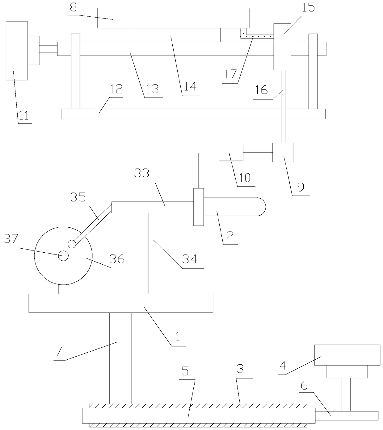
[0044] Embodiment 1, combining figure 1 :

[0045] The power supply mechanism also includes a second motor 11 and a first support frame 12, the first support frame 12 is provided with a first rotating shaft 13, the two ends of the first rotating shaft 13 are rotationally connected with the first support frame 12, the first A first support plate 14 is installed on the rotating shaft 13, and the solar cell panel 8 is installed on the first supporting plate 14; the second motor 11 is connected to the first rotating shaft 13, and the second motor 11 drives the first rotating shaft 13 to rotate; The rotation speed of the first rotating shaft 13 is 15 degrees per hour. When zero point, the solar cell panel 8 is horizontally arranged, and the surface of the solar cell panel 8 is arranged downward.

[0046] The second motor 11 drives the first rotating shaft 13 to rotate once a day. At zero o'clock, there is no sunlight. At 6 o'clock, the sun comes out, and the solar panel 8 rotates ...

Embodiment 2

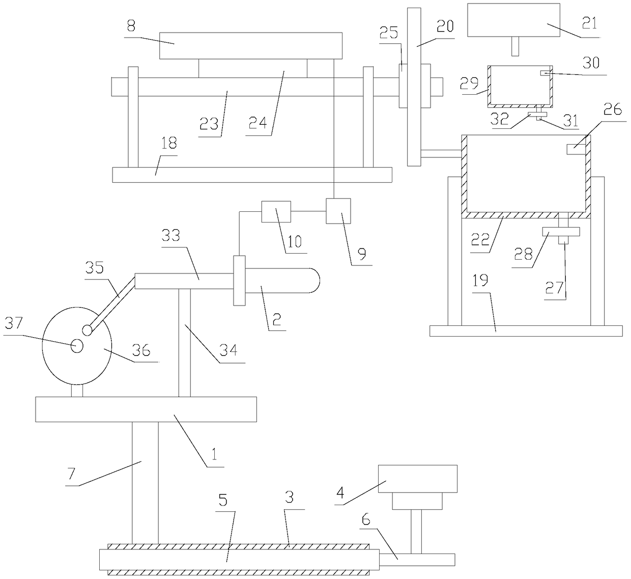
[0053] Example 2, combined with figure 2 :

[0054] The power supply mechanism also includes a second support frame 18, a third support frame 19, a rack 20, a dripping device 21, and a first container 22. The third support frame 19 is vertically provided with a chute, and the first The container 22 is slidably connected with the chute, and the friction force along the vertical direction between the first container 22 and the chute is equal to the gravity of the first container 22, and the first container 22 is connected with the rack 20; The strips 20 are arranged vertically.

[0055] This dripping device 21 is used for dripping medium in the first container 22, and the volume of this first container 22 is M liters, and the speed of this dripping device 21 adding medium is: Liters per hour; the dripping device 21 just fills up the medium in the first container 22 in one day.

[0056] The second supporting frame 18 is provided with a second rotating shaft 23, and the two e...


PUM


Abstract

The invention discloses a lighting electrical device which comprises a cross plate, a modulator tube, a supporting rod, a support, a connection rod and a rotating wheel. The support and the rotating wheel are arranged on the cross plate. The rotating wheel is connected with the cross plate in a rotating mode. The modulator tube is electrically connected with an external power source. The modulator tube is arranged at one end of the supporting rod. The middle of the supporting rod is connected with the support in a rotating mode. One end of the connection rod is hinged to the end, away from the modulator tube, of the supporting rod, and the other end of the connection rod is hinged to a non-center region of the rotating wheel. Certainly, in design, dead points should be avoided, and the length of the connection rod should be appropriate. According to the lighting electrical device, three-dimensional displacement of the modulator tube can be achieved, and the modulator tube is better in flexibility and more convenient to use; a solar cell panel is rotated continuously, the strength of sunlight shining onto the solar cell panel is made to be best, the sunlight utilization rate is increased, and the power supply effect is guaranteed; the lighting electrical device is simple in structure and convenient to use.

Description

technical field [0001] The invention relates to the technical field of lighting equipment, in particular to a lighting appliance. Background technique [0002] With the continuous improvement of the country's economy, people's requirements for the quality of life have also increased accordingly, transitioning from satisfying the conditions of daily life to enjoying life. As an indispensable object in life, lamps and lanterns can not only decorate the house but also provide light, which is more important. [0003] The use of existing lighting appliances is not flexible enough, and cannot be rotated at will, and needs further improvement. Contents of the invention [0004] In order to solve the technical problems existing in the background technology, the present invention proposes a [0005] A lighting appliance, including a horizontal plate, a lamp tube, a support rod, a bracket, a connecting rod, and a running wheel. The bracket and the running wheel are installed on th...

Claims


Application Information

Patent Timeline
Patent Type & Authority Patents(China)
IPC IPC(8): F21S9/03F21V23/06F21V25/00
CPCF21S9/032F21V23/06F21V25/00
Inventor 张宏标
Owner 芜湖市启安电气科技有限责任公司
Learn More