
Numerically-controlled edge grinding machine for irregular glass

A special-shaped glass and edge grinding machine technology, which is applied in the direction of grinding frames, machine tools suitable for grinding workpiece edges, grinding machine parts, etc. requirements and other issues to achieve the effect of realizing three-dimensional displacement and improving edge grinding accuracy

Inactive Publication Date: 2017-06-13
戴巧
View PDF0 Cites 2 Cited by
  • Summary
  • Abstract
  • Description
  • Claims
  • Application Information

AI Technical Summary

Problems solved by technology

[0002] In order to meet various needs, glass products and glass mirror products are made into different shapes of beveled edges, round edges and wavy edges. The traditional technology is usually realized by manual edging, which is difficult to meet the requirements of high precision and large quantities. Time-consuming

Method used


Image

  • Numerically-controlled edge grinding machine for irregular glass

Examples


Embodiment 1

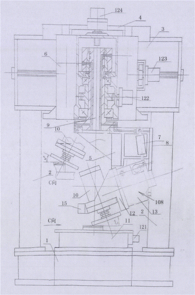
[0019] Such as figure 1 As shown, the present invention provides a CNC special-shaped glass edging machine including a bed 1, a rotary table 11 is arranged above the bed 1, an edging unit 108 is suspended above the rotary table 11, and the edging unit 108 is suspended by the beam 3 and the column 2. Located above the rotary table 11, the column 2 is fixed on both sides of the bed 1, the column 2 is vertically arranged, the beam 3 is fixedly connected between the columns 2 on both sides, and is located above the rotary table 11, and the beam 3 is arranged horizontally.

[0020] As preferably, the transverse slide plate 4 is set on the crossbeam 3, and the third displacement mechanism 123 is arranged on the transverse slide plate 4, and the third displacement mechanism 123 includes a transverse drive mechanism and a transverse transmission mechanism for realizing power transmission between the transverse drive mechanism and the transverse slide plate 4, The crossbeam 3 and the t...

Embodiment 2

[0029] The CNC special-shaped glass edging machine provided by Embodiment 2 of the present invention has basically the same structure as that in Embodiment 1, and the difference lies in:

[0030] As preferred, in this embodiment of the present invention, such as figure 1 As shown, a rectangular slide table 11 is arranged above the bed 1, and the slide table 11 is slidably connected with the bed 1. The rectangular slide table 11 is driven to move back and forth longitudinally by the first displacement mechanism 121. The first displacement mechanism 121 includes a longitudinal displacement drive. mechanism and the longitudinal displacement transmission mechanism that realizes the transmission between the longitudinal displacement drive mechanism and the slide plate workbench 11. Preferably, in this embodiment of the present invention, the slide table 11 and the bed 1 are connected through a ball guide rail or a ball screw, and the longitudinal displacement driving mechanism is a...


PUM


Abstract

The invention provides a numerical control special-shaped glass edging machine, which includes a bed, a rotary table is set above the bed, the rotary table is driven by a first displacement mechanism to rotate clockwise or counterclockwise, a beam is set above the bed, and a transverse beam is set on the beam Skateboard, the horizontal slideboard is driven by the third displacement mechanism to move back and forth horizontally; the vertical slideboard is set on the horizontal slideboard, and the vertical slideboard is driven by the vertical up and down displacement mechanism to move vertically up and down; the vertical slideboard is provided with an indexing axis, and the indexing axis passes through the second displacement mechanism Drive to achieve clockwise or counterclockwise rotation, the first displacement mechanism, the second displacement mechanism, the third displacement mechanism and the vertical up and down displacement mechanism realize four-axis linkage under the numerical control, and the large end surface of the indexing axis hangs the edging unit. The technical solution disclosed by the invention not only realizes three-dimensional displacement, but also realizes the precise adjustment of the angle of the edging unit and the precise adjustment of the inclination of the edging, improves the edging precision, and realizes the numerical control automatic edging of special-shaped glass.

Description

technical field [0001] The invention relates to a glass processing machine, in particular to a numerical control special-shaped glass edging machine which realizes high precision and is convenient for mass processing. Background technique [0002] In order to meet various needs, glass products and glass mirror products are made into different shapes of beveled edges, round edges and wavy edges. The traditional technology is usually realized by manual edging, which is difficult to meet the requirements of high precision and large quantities. Time-consuming. Contents of the invention [0003] In order to overcome the above-mentioned problems in the prior art, the present invention provides a numerical control special-shaped glass edging machine which improves the edging precision and adapts to various shapes. [0004] A CNC special-shaped glass edging machine provided by the present invention includes a bed, and a rotary table is arranged above the bed. The rotary table is ...

Claims


Application Information

Patent Timeline
Patent Type & Authority Applications(China)
IPC IPC(8): B24B9/08B24B41/02B24B47/22
CPCB24B9/08B24B41/02B24B47/22
Inventor 戴巧
Owner 戴巧
Learn More