A furnace cover lifting mechanism and a nitriding furnace using the mechanism

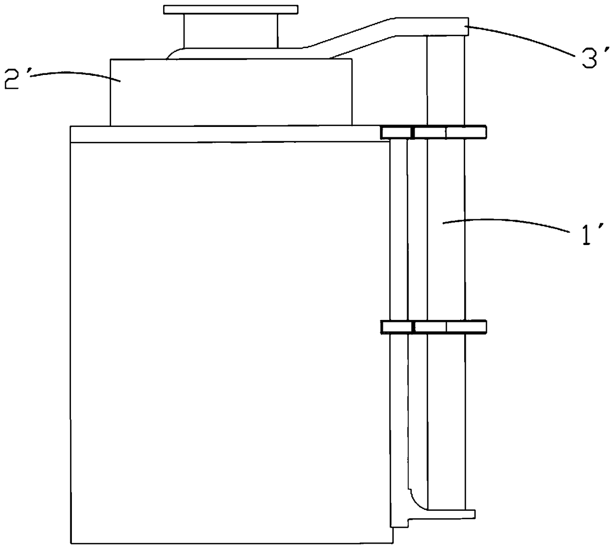
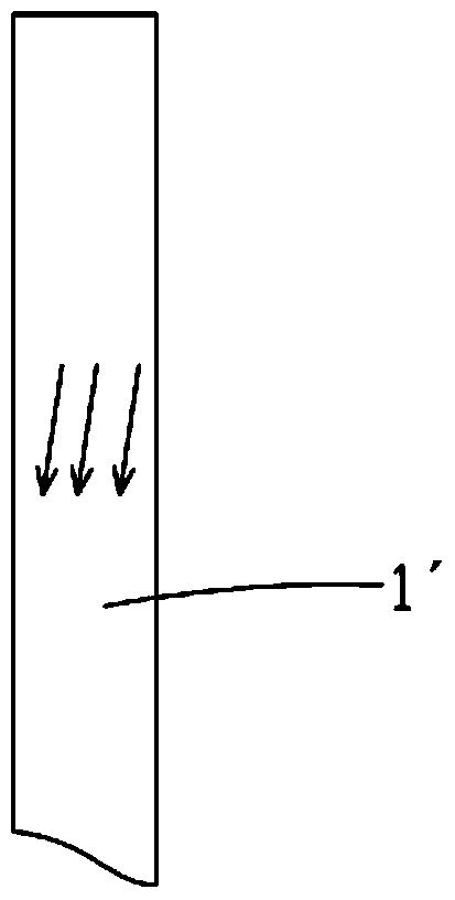
A lifting mechanism and furnace cover technology, which is applied in the field of nitriding furnaces, can solve problems such as unstable shaking of the furnace cover 2′, potential safety hazards, and reduced rigidity of the lifting shaft, so as to ensure rigidity and strength, eliminate distortion and deformation force, The effect of improving stability

Inactive Publication Date: 2018-08-17
长沙赛飞斯金属科技有限公司
View PDF9 Cites 0 Cited by
  • Summary
  • Abstract
  • Description
  • Claims
  • Application Information

AI Technical Summary

Problems solved by technology

like figure 1 As shown, the lifting mechanism of the traditional nitriding furnace cover is that the hydraulic cylinder drives the lifting shaft 1' to drive the furnace cover 2' to move up and down, so as to realize the opening and closing of the furnace cover 2'. The lifting mechanism adopts a lifting shaft 1' to realize The up and down movement of the furnace cover 2', because the furnace cover 2' is connected to the top of the lifting shaft 1' through the bracket 3' produces a large cantilever moment, which requires high rigidity of the lifting shaft 1' and the performance of the hydraulic cylinder. As the number of uses increases, the rigidity of the lifting shaft decreases, such as figure 2 As shown, the lifting shaft 1' is distorted and deformed due to the change of force, which causes the furnace cover 2' to shake unsteadily or even fail to lift, the hydraulic cylinder is severely worn, the service life of the equipment is greatly reduced, and potential safety hazards are likely to occur. The larger the cover, the more serious the above problems

Method used


Image

  • A furnace cover lifting mechanism and a nitriding furnace using the mechanism
  • A furnace cover lifting mechanism and a nitriding furnace using the mechanism
  • A furnace cover lifting mechanism and a nitriding furnace using the mechanism

Examples


Embodiment 1

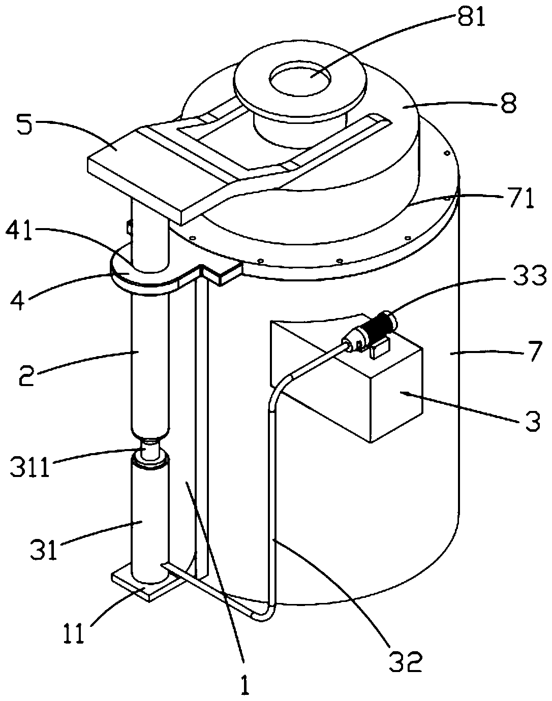
[0029] Such as image 3 and Figure 4 As shown, the present invention provides a furnace cover lifting mechanism, which includes a guide seat 1, a guide column 2 and a hydraulic lifting mechanism 3 for supporting the guide column 2 to lift. The guide seat 1 is provided with a first shaft perpendicular to it. Seat 4, the first shaft seat 4 is provided with a first shaft hole 41 matching the shape of the guide post 2, the guide post 2 vertically passes through the first shaft hole 41 and is slidably fitted in the first shaft seat 4, Its top is fixedly connected with the connecting crossbeam 5 that one end is connected with furnace cover 8 . The bottom end of the guide seat 1 extends outward horizontally to form a support 11. The hydraulic lifting mechanism 3 includes a hydraulic cylinder 31, an oil pipe 32 and an electric hydraulic pump 33. The hydraulic cylinder 31 is vertically installed on the support 11. The electric hydraulic pump 33 is connected, and the lifting shaft 31...

Embodiment 2

[0034] Such as Figure 6 As shown, the components that are the same as or corresponding to those in the first embodiment are marked with the corresponding reference numerals in the first embodiment. For the sake of simplicity, only the differences from the first embodiment will be described below. This embodiment two and image 3The difference of the first embodiment shown is that in this embodiment, the guide seat 1 is also provided with a second shaft seat 9, which is sleeved on the outside of the hydraulic cylinder 31 to further increase the hydraulic cylinder capacity. 31 for strength and firmness. At the same time, a third shaft seat 10 is also provided on the guide seat 1, and the third shaft seat 10 is sleeved on the outside of the guide column 2 and placed under the first shaft seat 4, wherein the first shaft seat 4, the second shaft seat The second shaft seat 9, the third shaft seat 10 and the support 11 are all arranged in parallel and located in the same vertical ...


PUM


Abstract

The invention relates to a furnace cover lifting mechanism and a nitrogenation oven with the mechanism. The furnace cover lifting mechanism comprises a guiding base, a guiding column and a hydraulic lifting mechanism used for supporting the guiding column to rise and fall. The guiding base is provided with a first shaft base perpendicular to the guiding base. The guiding column is in sliding fit in the first shaft base. The top end of the guiding column penetrates the first shaft base to be fixedly connected with a connecting beam with one end connected with a furnace cover. The bottom end of the guiding base horizontally extends out to form a support. The hydraulic lifting mechanism comprises a hydraulic oil cylinder, an oil pipe and an electric hydraulic pump. The hydraulic oil cylinder is installed on the support and communicated with the electric hydraulic pump through the oil pipe. A lifting shaft of the hydraulic oil cylinder is connected with the guiding column through a spherical steel ball. The guiding column and the lifting shaft are movably connected through the spherical steel ball. The stress situation of the guiding column and the lifting shaft in the furnace cover opening and closing driving process can be automatically adjusted, the distortion deformation is eliminated, rigidity of the guiding column and the lifting shaft is effectively guaranteed, the stability in the lifting process is improved, and the service life of the overall structure is prolonged.

Description

Technical field: [0001] The invention relates to the technical field of industrial furnaces, in particular to a furnace cover lifting mechanism and a nitriding furnace using the mechanism. Background technique: [0002] A few days ago, due to the high temperature performance of the nitriding furnace, the furnace cover is required to be insulated, which makes its weight often heavy. In the process of use, the furnace cover needs to be opened to check the state of the furnace. Such as figure 1 As shown, the lifting mechanism of the traditional nitriding furnace cover is that the hydraulic cylinder drives the lifting shaft 1' to drive the furnace cover 2' to move up and down, so as to realize the opening and closing of the furnace cover 2'. The lifting mechanism adopts a lifting shaft 1' to realize The up and down movement of the furnace cover 2', because the furnace cover 2' is connected to the top of the lifting shaft 1' through the bracket 3' produces a large cantilever mom...

Claims


Application Information

Patent Timeline
Patent Type & Authority Patents(China)
IPC IPC(8): F27D1/18
Inventor 叶玉芳叶华健
Owner 长沙赛飞斯金属科技有限公司
Why Eureka
Try Eureka