Hybrid Current Sensor Assembly

A technology of current sensor and hall sensor, which is applied to the components of electrical measuring instruments, measuring current/voltage, instruments, etc., which can solve the problems of production cost and product volume increase

Active Publication Date: 2015-11-11
TYCO ELECTRONICS AMP KOREA
View PDF10 Cites 14 Cited by
  • Summary
  • Abstract
  • Description
  • Claims
  • Application Information

AI Technical Summary

Problems solved by technology

Therefore, production cost and product volume increas

Method used


Image

  • Hybrid Current Sensor Assembly
  • Hybrid Current Sensor Assembly
  • Hybrid Current Sensor Assembly

Examples


Embodiment Construction

[0034] Hereinafter, some example embodiments will be described in detail with reference to the accompanying drawings. With regard to the reference numerals assigned to elements in the figures, it should be noted that, wherever possible, the same elements will be designated by the same reference numerals, even if shown in different figures. Likewise, in the description of the embodiments, when it is considered that a detailed description of a well-known related structure or function would cause an obscure explanation of the present disclosure, such description will be omitted.

[0035] Additionally, terms such as first, second, A, B, (a), (b), etc., may be used herein to describe components. Each of these terms is not used to define an element, order, or sequence of the corresponding member, but merely to distinguish the corresponding member from the other member(s). It should be noted that if a member is described in the specification as being "connected", "coupled" or "coupl...


PUM


Abstract

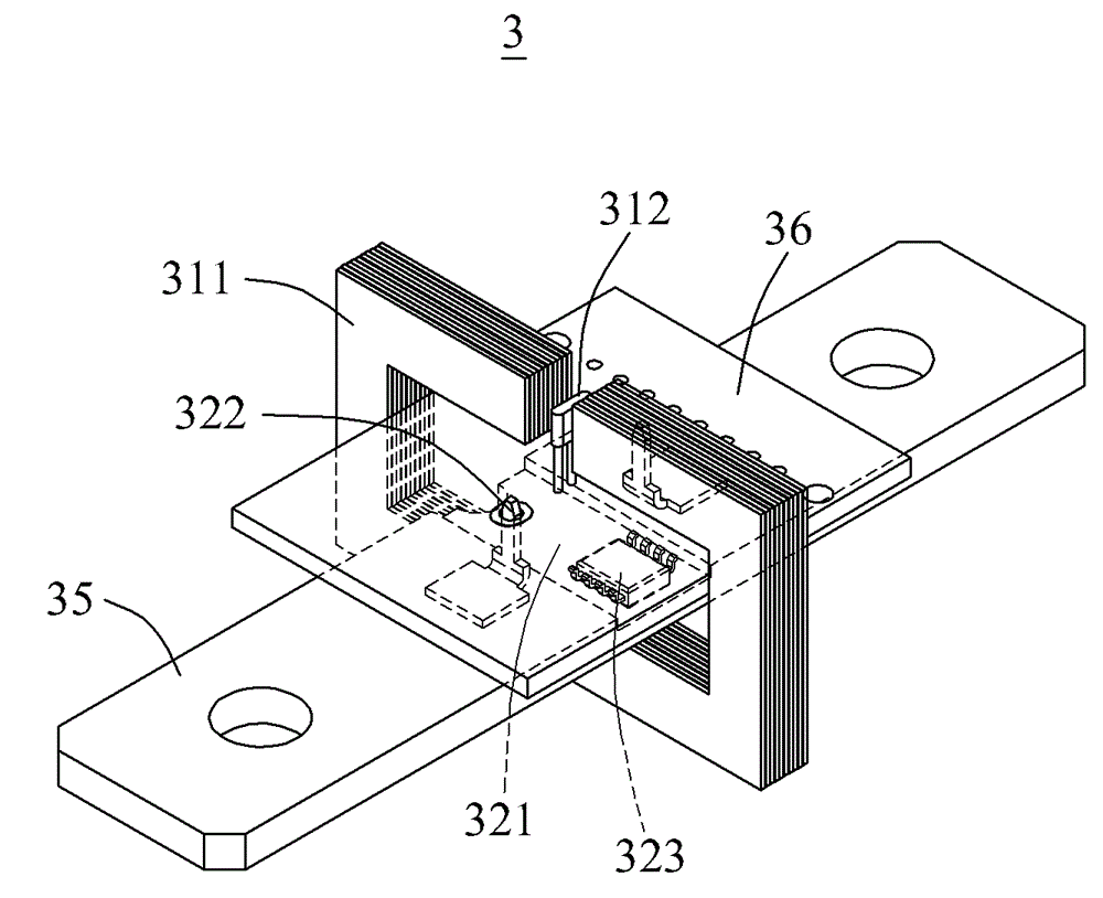
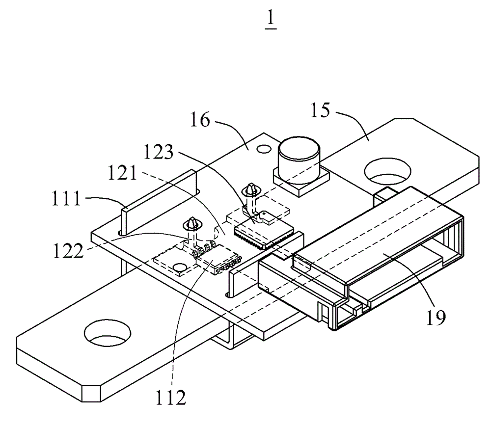
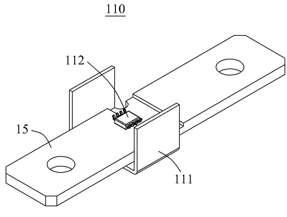
Provided is a hybrid current sensor assembly (1) ncluding a conductor (15) to be connected to both terminals of an external electronic device, a Hall core (111) to which a magnetic field generated by a current flowing in the conductor (15) is applied, a Hall sensor (112) in which a potential difference occurs at both ends thereof due to the magnetic field applied to the Hall core (111), a shunt terminal (122) configured to shunt the current flowing in the conductor (15), and a microprocessor (123) connected to the shunt terminal (122) and configured to measure the current flowing in the conductor (15).

Description

[0001] Cross References to Related Applications [0002] This application claims acknowledgment of Korean Patent Application No. 10-2014-0050656 filed with the Korean Intellectual Property Office on April 28, 2014 and Korean Patent Application No. 10-2014- filed with the Korean Intellectual Property Office on September 18, 2014 0124358, the disclosures of which are incorporated herein by reference. technical field [0003] The present invention relates to hybrid current sensor assemblies. Background technique [0004] A current sensor is an electronic component that senses current. Current sensors are available in various types such as Hall sensors and shunt sensors. [0005] The Hall effect refers to the physical phenomenon in which a potential difference appears across a conductor through which a current flows when a magnetic field interconnects the conductor. The potential difference induced due to such a Hall effect is proportional to the interconnected magnetic field...

Claims


Application Information

Patent Timeline
IPC IPC(8): G01R19/00
CPCG01R15/183G01R1/203G01R15/202G01R15/207G01R15/08G01R15/142G01R15/146
Inventor 蔡鸿一崔庾植姜信郁金荣云
Owner TYCO ELECTRONICS AMP KOREA
Why Eureka
Try Eureka