A Personalized Service System Based on Electronic Control Unit of EFI Engine
A technology of electronic control unit and service system, applied in the field of wireless communication, cloud computing, and automotive electronics, can solve the problems of batch storage, analysis, and improvement suggestions of raw data streams, so as to reduce code workload, improve stability, and accuracy high degree of effect
- Summary
- Abstract
- Description
- Claims
- Application Information
AI Technical Summary
Problems solved by technology
Method used
Image
Examples
Embodiment 1
[0041] Embodiment 1 Overall system structure of the present invention
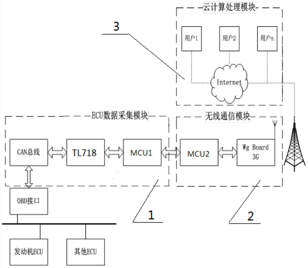
[0042] refer to figure 1 , a kind of personalized service system based on the electronic control unit (ECU) of electric spray engine of the present invention, structure has ECU data collection module 1, wireless communication module 2, cloud computing processing module 3. Among them, ECU data acquisition module 1 mainly includes CAN bus transceiver chip model PCA82C250, OBD data acquisition interface chip TL718, and single-chip microcomputer I model MSP430F149; wireless communication module 2 mainly includes single-chip microcomputer II model S3C2440 or S3C2440A and WgBoard 3G module ; The ECU data acquisition module 1 and the wireless communication module 2 are connected through the serial port of the single-chip microcomputer Ⅰ and the single-chip microcomputer Ⅱ to realize the communication process, and realize the data transmission through the base station; the cloud computing processing module 3 mainl...
Embodiment 2
[0043] Embodiment 2 TL718 configuration and interface circuit of the present invention
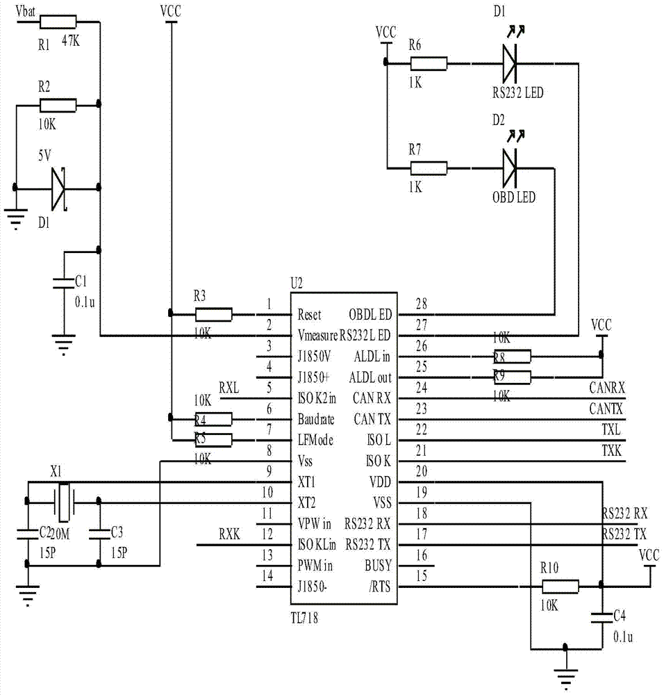
[0044] refer to figure 2 , the TL718 configuration and interface circuit structure of the present invention are: pin 1, pin 6, and pin 7 of TL718 are connected to VCC through resistors R3, R4 and R5, pin 2 is grounded through a Zener diode, and resistor R2 is connected in parallel with capacitors C1 and R2 The other end of the terminal is connected to Vbat through R1, pin 9 is grounded through C2, pin 10 is grounded through C3, and the crystal oscillator X1 is connected between pins 9 and 10, pin 8 is grounded, and pins 27 and 28 are respectively connected to light-emitting diodes D1, D2 and resistors. R3, R6 are connected to VCC, pins 15, 25, and 26 are connected to VCC through resistors R19, R11, and R12, pin 19 is grounded, pins 5, 12, 21, and 22 are respectively connected to RXL, RXK, and TXL, TXK, pins 23 and 24 are respectively connected to the TXD port and RXD port of the CAN bus ...
Embodiment 3
[0045] Embodiment 3 The peripheral configuration circuit supplemented by TL718 of the present invention
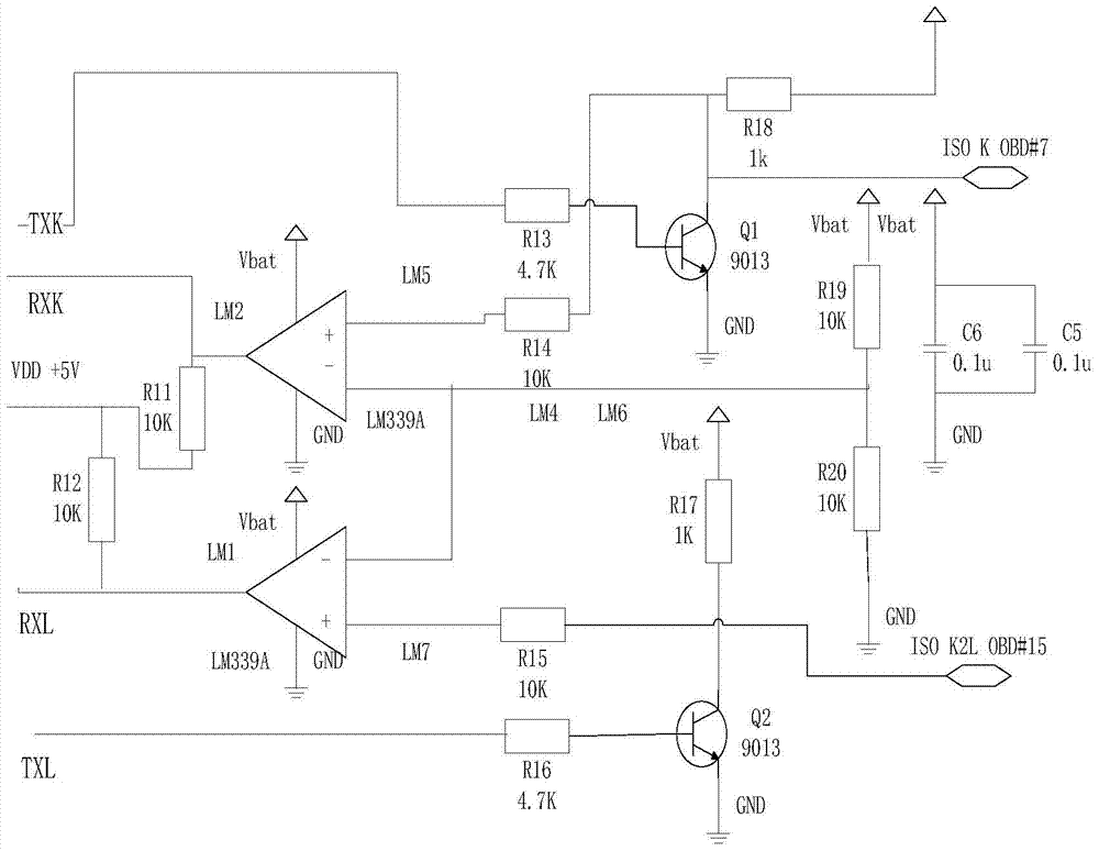
[0046] refer to image 3 , the supplementary peripheral configuration circuit diagram structure of the TL718 of the present invention is: the 21 pins of TL718 are connected to the base of the transistor Q1 through the resistor R13, the collector of the transistor Q1 is connected to Vbat through the resistor R18, and the collector of the transistor Q1 is connected to the OBD#7 port, and the collector of the transistor Q1 is connected to the OBD#7 port of the TL718 Pin 5 and pin 12 are respectively connected to comparator LM1 and comparator LM2 through resistors R12 and R11. One end of resistor R14 is connected to the positive port of comparator LM2, and the other end is connected to Vbat through resistor R18. The negative ports of the two comparators are connected, and the negative port passes through Resistor R19 is connected to Vbat and grounded through resistor R20 at th...
PUM
 Abstract
Description
Claims
Application Information
 - R&D
- Intellectual Property
- Life Sciences
- Materials
- Tech Scout
- Unparalleled Data Quality
- Higher Quality Content
- 60% Fewer Hallucinations
Browse by: Latest US Patents, China's latest patents, Technical Efficacy Thesaurus, Application Domain, Technology Topic, Popular Technical Reports.
© 2025 PatSnap. All rights reserved.Legal|Privacy policy|Modern Slavery Act Transparency Statement|Sitemap|About US| Contact US: help@patsnap.com


