Single-wire transmission interface and single-wire transmission method and power supply system adopting single-wire transmission method

A transmission method and transmission line technology, applied in the field of power supply systems, can solve problems such as the inability to define the length of transmission time, the inability to transmit frequency, etc.

Active Publication Date: 2015-11-11
RICHTEK TECH
View PDF5 Cites 8 Cited by
  • Summary
  • Abstract
  • Description
  • Claims
  • Application Information

AI Technical Summary

Problems solved by technology

In this case, since the frequency cannot be communicated, the length of time to transmit a bit

Method used


Image

  • Single-wire transmission interface and single-wire transmission method and power supply system adopting single-wire transmission method
  • Single-wire transmission interface and single-wire transmission method and power supply system adopting single-wire transmission method
  • Single-wire transmission interface and single-wire transmission method and power supply system adopting single-wire transmission method

Examples


Embodiment Construction

[0092] The foregoing and other technical contents, features and effects of the present invention will be clearly presented in the following detailed description of a preferred embodiment with reference to the drawings. The drawings in the present invention are all schematic, mainly intended to show the functional relationship between each device and each component, as for the shape, size, and direction, they are not drawn according to the scale of the actual object.

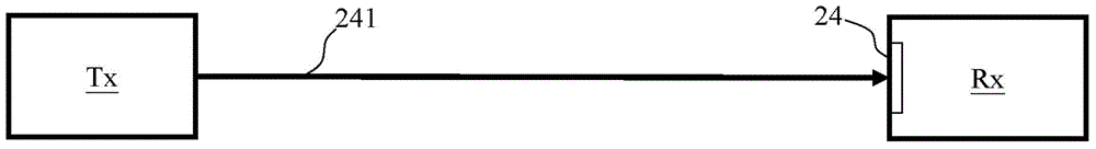
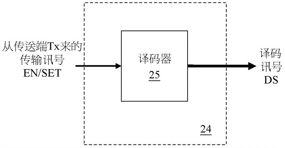
[0093] Please refer to figure 1 , which shows a schematic block diagram of the single transmission line transmission method of the present invention. Such as figure 1 As shown, the transmitting end Tx sends signals to the receiving end Rx through a single transmission line 241 . The receiving end Rx has a single transmission line interface 24 for decoding the received signal. When the transmitting end Tx transmits a signal to the receiving end Rx, it must follow the predefined communication protocol between th...


PUM


Abstract

The present invention discloses a single-wire transmission method, which includes: providing a transmission signal including alternating high and low levels through a single-wire, wherein a period of one of the high and low levels defining a reference time and a period of the other of the high and low levels defining a content time; determining a relative relationship between the reference time and the content time; when the content time is smaller than a proportion of the reference time, defining the content time to express a first meaning; and when the content time is larger than the proportion of the reference time, defining the content time to express a second meaning.

Description

technical field [0001] The present invention relates to a single transmission line transmission interface and a single transmission line transmission method and a power supply system using the single transmission line transmission method, in particular to a single transmission line transmission interface and a single transmission line transmission method applicable to power charging cables, and A power supply system using a single transmission line transmission method. Background technique [0002] A power supply system in the prior art includes a power converter and a power charging cable (hereinafter referred to as the cable) for supplying power to an electronic device. The cable contains positive and negative power lines (Vbus and GND) and positive and negative data lines (D+ and D-). When the power converter and cable are connected to the electronic device, the positive and negative power lines are responsible for transmitting power, while the positive and negative data...

Claims


Application Information

Patent Timeline
IPC IPC(8): G06F13/40G06F13/42
CPCH04L7/044H04B3/542H04L25/4906H04L25/4902
Inventor 陈曜洲
Owner RICHTEK TECH
Why Eureka
Try Eureka