Intelligent terminal blind plug interface device and interface control method

A technology of intelligent terminal and interface device, which is applied to the parts of the connection device, coupling device, circuit device, etc., can solve the problems of core insertion and disconnection of the female seat, power consumption, and overcharging of the mobile terminal battery, so as to avoid overcharging. problems, easy data connection, the effect of improving the lifespan

Active Publication Date: 2017-11-10
NINGBO SAGEREAL COMM
View PDF6 Cites 0 Cited by
  • Summary
  • Abstract
  • Description
  • Claims
  • Application Information

AI Technical Summary

Problems solved by technology

When the old people are using it, if they are not careful, it is easy to insert the deviation, and what's more, it is easy to break the core of the female seat, so as to design the female seat with an iron tongue, which increases the cost, but it cannot fundamentally solve the problem. above question
When charging, the charger is generally connected to the mobile terminal. Even if it is fully charged, the charger is still working. One is power consumption, and the other is easy to cause overcharging of the mobile terminal battery and shorten the battery life.

Method used


Image

  • Intelligent terminal blind plug interface device and interface control method
  • Intelligent terminal blind plug interface device and interface control method
  • Intelligent terminal blind plug interface device and interface control method

Examples


Embodiment 1

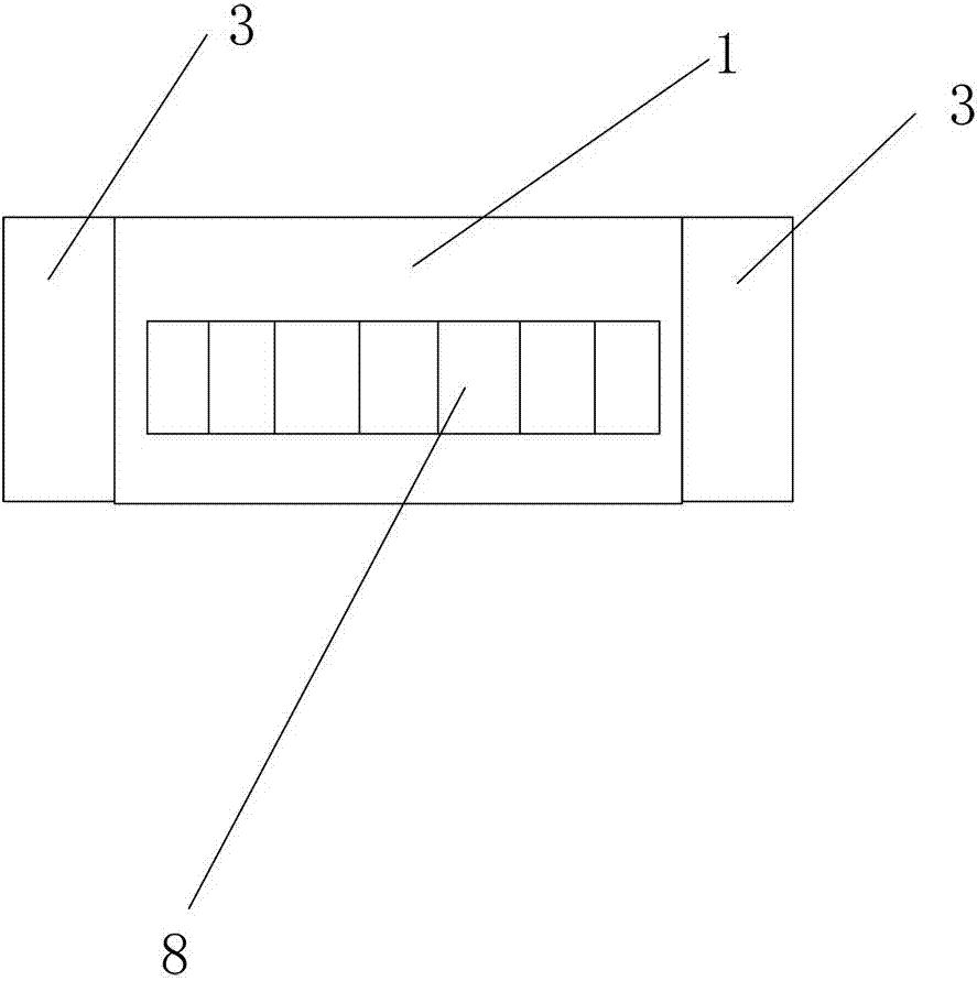
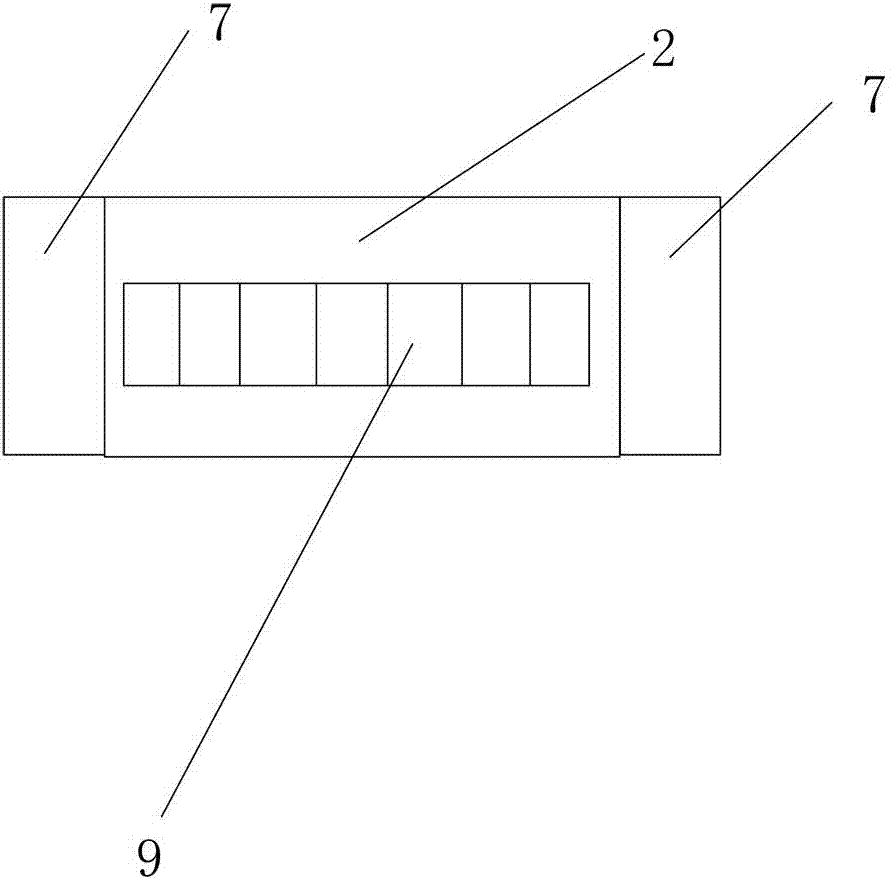
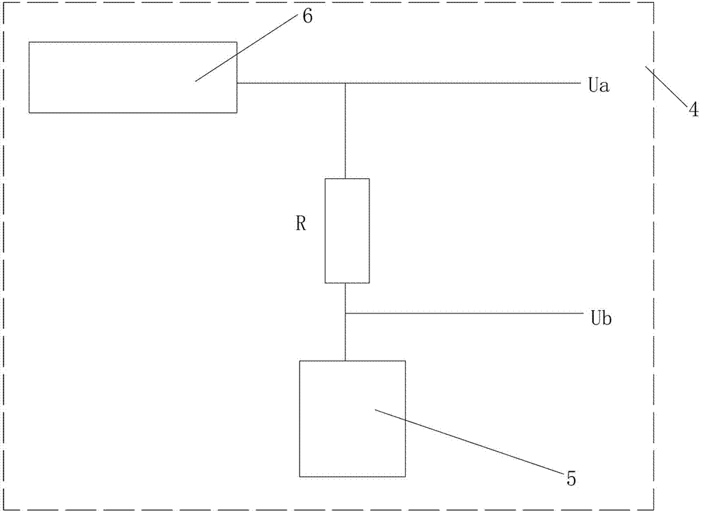
[0021] Such as figure 1 , figure 2 , image 3 As shown, the intelligent terminal blind plug interface device described in this embodiment includes a mobile terminal female seat 1 and a mobile terminal male seat 2 that cooperates with the mobile terminal female seat 1 to realize the charging mode. Both sides are symmetrically provided with a magnet rotating device 3 that changes the magnetism of the internal magnet after rotation, and a first magnet 15 is provided on the left and right sides of the mobile terminal male seat 2, and the N pole of the first magnet 15 faces outward, so The default magnetism corresponding to the magnet rotating device 3 and the first magnet 7 is the S pole, and the definition of each pin of the mobile terminal male seat 2 and the definition of each pin of the mobile terminal female seat 1 are one-to-one correspondence. The magnet rotation device 3 is connected with a current detection device 4 that controls the rotation of the magnet rotation dev...

Embodiment 2

[0024] Such as Figure 4 As shown, the smart terminal blind plug interface device described in this embodiment is different from Embodiment 1 in that in order to achieve a real blind plug effect, a row of female socket interfaces 8 is customized on the female socket 1 of the mobile terminal. The mobile terminal public seat 2 is customized with two rows of public seat interfaces 9 distributed up and down, and the names of the upper row of public seat interfaces 9-1 in the mobile terminal public seat 2 from left to right are the same as those defined by the mobile terminal public seat 2 The names of the definitions of the pins from right to left in the middle and lower rows of male seat interfaces 9-2 are consistent, and the definitions of the pins of the upper row of male seat interfaces 9-1 in this embodiment are the same as those of the female socket 1 of the mobile terminal. One to one correspondence.

[0025]In the above, the names defined by the pins of the upper row of m...

Embodiment 3

[0028] Such as Figure 7 As shown, the smart terminal blind plug interface device described in this embodiment is different from Embodiment 1 in that: the magnet rotation device 3 includes a fixed frame 14 and a magnet rotation control system arranged in the fixed frame 14, so The magnet rotation control system includes a controller 10, a micro-motor 11, a rotating shaft 12, and a central magnet 13 located in the rotating shaft 12. The two signal detection terminals of the controller 10 are connected to the first detection point Ua and the second detection point Ua respectively. The detection point Ub is connected, the output end of the controller 10 is connected with the micromotor 11 , and the output shaft of the micromotor 11 is connected with the rotating shaft 12 . When the above design works, when the mobile terminal male seat 2 and the mobile terminal female seat 1 are attracted together, the charging function is realized. At this time, the controller 10 monitors the ch...


PUM


Abstract

An intelligent terminal blind plug interface device and an interface control method disclosed in the present invention include a mobile terminal female seat and a mobile terminal male seat, and magnet rotating devices are symmetrically arranged on the left and right sides of the mobile terminal female seat. There are magnets on the left and right sides of the male seat, and the N poles of the magnets face outwards. The default magnetism corresponding to the magnet rotating device and the first magnet is the S pole. The definition name and movement of each pin of the male seat of the mobile terminal The definition name of each pin of the terminal base is one-to-one correspondence. A current detection device that controls the rotation of the magnet rotation device is connected to the magnet rotation device. The resistor in the current detection device is connected between the battery and the charging circuit. The connection point between the resistor and the charging circuit is used as the first detection point, and the connection point between the resistor and the battery is used as the second detection point. The invention has an automatic power-off pop-up device, avoids the problem of overcharging of the mobile terminal, improves the service life of the battery, and at the same time, the user can easily realize data connection.

Description

technical field [0001] The invention relates to a charging interface, in particular to an intelligent terminal blind plug interface device and an interface control method. Background technique [0002] With the development of society, people have higher and higher requirements on the usability of mobile terminals. But currently, when charging and connecting data to the mobile terminal, the user needs to hold the corresponding data connector, align it with the female socket of the terminal, and insert it carefully so as not to damage the interface. When the old people are using it, if they are not careful, it is easy to insert the deviation, and what's more, it is easy to break the core of the female seat, so as to design the female seat with an iron tongue, which increases the cost, but it cannot fundamentally solve the problem. above question. When charging, the charger is generally connected to the mobile terminal. Even if it is fully charged, the charger is still workin...

Claims


Application Information

Patent Timeline
Patent Type & Authority Patents(China)
IPC IPC(8): H02J7/00H02H7/18H01R13/629
Inventor 林水明范超群李明英董吉正王梁洁
Owner NINGBO SAGEREAL COMM
Why Eureka
Try Eureka