Supercharge Your Innovation With Domain-Expert AI Agents!

Novel kinetic energy machine system

A kinetic energy machine and a new type of technology, applied in the field of kinetic energy machines, can solve the problems of high cost, low energy conversion rate, and inability to achieve sustainable utilization.

Inactive Publication Date: 2015-11-11
邓文科
View PDF0 Cites 1 Cited by
  • Summary
  • Abstract
  • Description
  • Claims
  • Application Information

AI Technical Summary

Problems solved by technology

Its cost is high and the energy conversion rate is low
Also, it is not sustainable for burning fossil fuels, which are most commonly used today

Method used


Image

  • Novel kinetic energy machine system
  • Novel kinetic energy machine system

Examples


Embodiment Construction

[0027] The present invention will be described in further detail below in conjunction with the accompanying drawings.

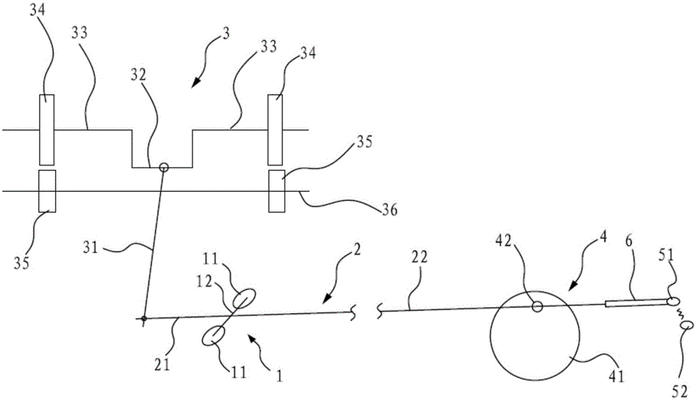
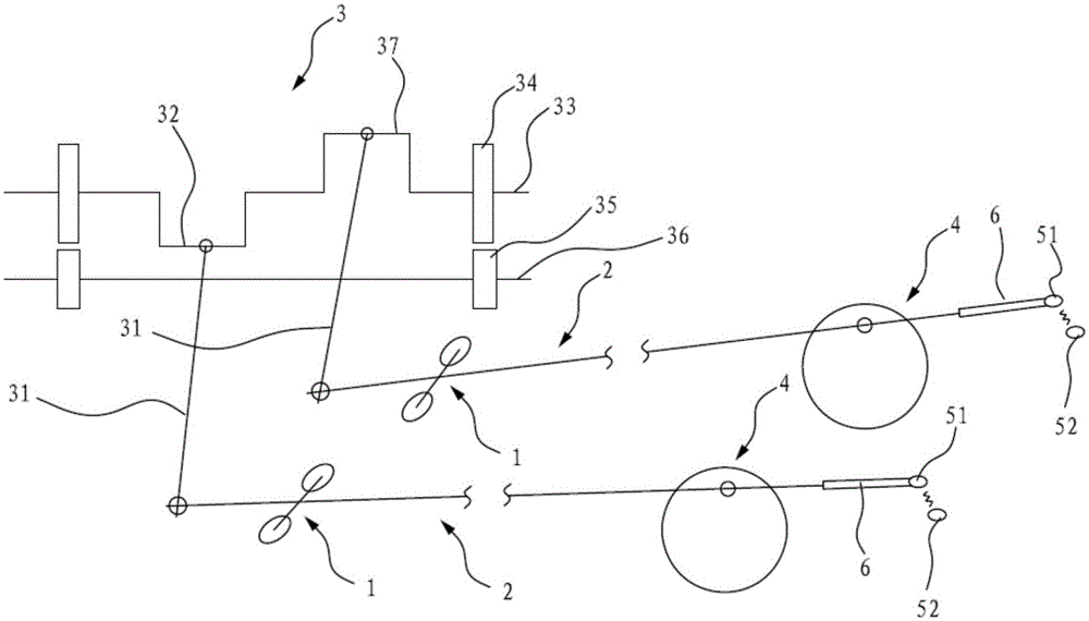
[0028] Such as figure 1 As shown, a novel kinetic energy machine 3 system according to an embodiment of the present invention is schematically shown, which includes a fulcrum 1, a lever 2, a kinetic energy machine 3 and a power source 4; wherein, the fulcrum 1 is used to support the lever 2; The lever 2 is divided into a first rod body 21 and a second rod body 22 with the fulcrum 1 as the boundary, and the length of the second rod body 22 is greater than the length of the first rod body 21; the kinetic energy machine 3 is connected with the end of the first rod body 21 away from the fulcrum 1; the power source 4 is connected to the end of the second rod body 22 away from the fulcrum 1; the power source 4 drives the end of the second rod body 22 to move away from the fulcrum 1, and the second rod body 22 drives the end of the first rod body 21 away from the fu...


PUM


Abstract

The invention discloses a novel kinetic energy machine system which comprises a support point, a lever, a kinetic energy machine and a power source, wherein the support point is used for supporting the lever, the lever is divided into a first lever body and a second lever body by taking the support point as a boundary, the length of the second lever body is greater than the length of the first lever body, the kinetic energy machine is connected with one end, far away from the support point, of the first lever body, the power source is connected with one end, far away from the support point, of the second lever body and drives the second lever body to move along one end far away from the support point, the second lever body drives the first lever body to move along one end far away from the support point through a lever principle, the second lever body moves so as to drive the kinetic energy machine to move, and the moving direction of one end, far away from the support point, of the first lever body is opposite to the moving direction of one end, far away from the support point, of the second lever body. In the whole kinetic energy system, the lever principle is ingeniously utilized, and thus, a small power source can be used for driving a larger kinetic energy machine to work.

Description

technical field [0001] The invention relates to the field of kinetic energy machines, in particular to a novel kinetic energy machine system. Background technique [0002] After the kinetic energy machine is driven to move, the kinetic energy of the kinetic energy machine can be used to generate electricity. However, traditional kinetic energy machines all need to use wind energy, solar energy, nuclear energy, and burning fossil fuels to obtain kinetic energy. Its cost is high, and energy conversion rate is low. And it's not sustainable in the way fossil fuels are most commonly burned today. Contents of the invention [0003] The object of the present invention is to provide a novel kinetic energy machine system, which can solve at least one of the above-mentioned problems. [0004] According to one aspect of the present invention, a novel kinetic energy machine system is provided, including a fulcrum, a lever, a kinetic energy machine and a power source; [0005] The ...

Claims


Application Information

Patent Timeline
Patent Type & Authority Applications(China)
IPC IPC(8): H02K53/00
Inventor 邓文科
Owner 邓文科
Features
  • R&D
  • Intellectual Property
  • Life Sciences
  • Materials
  • Tech Scout
  • Unparalleled Data Quality
  • Higher Quality Content
  • 60% Fewer Hallucinations
Learn More