Simple screw clamping mechanism

A clamping mechanism, screw technology

Inactive Publication Date: 2015-11-18
CHONGQING JIANAN IND & TRADE
View PDF1 Cites 3 Cited by
  • Summary
  • Abstract
  • Description
  • Claims
  • Application Information

AI Technical Summary

Problems solved by technology

The advantage of the screw clamping mechanism is to prevent a large force from being generated during clamping, thereby protecting the workpiece from being damaged. The disadvantage is that the structure of the clamping mechanism is relatively complicated, and welding technology is used. Once the parts are damaged, hard to replace

Method used


Image

  • Simple screw clamping mechanism

Examples


Embodiment Construction

[0010] The present invention will be further described in detail below in conjunction with the accompanying drawings and specific embodiments.

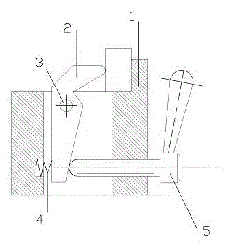
[0011] like figure 1 As shown, the present invention includes a base 1, the base 1 is provided with a vertical hollow part, a clamping block 2 is arranged in the hollow part, and the upper end of the clamping block 2 is fixed on the hollow part of the base 1 by a positioning pin 3 , the lower end of the clamping block 2 is connected to one side of the base 1 through a spring 4 , and a handle 5 is provided on the other side of the base 1 opposite to the spring 4 .

[0012] In the present invention, through the inward rotation of the handle 5, the clamping block 2 is squeezed, so that the upper end of the clamping block 2 clamps the workpiece to play a clamping role. On the contrary, when the handle 5 is rotated outwards, the spring 4 exerts an elastic force on the clamping block 2 to drive the clamping block 2 to loosen the workpiece,...


PUM


Abstract

The invention relates to a tool clamp in machining, and in particular to a simple screw clamping mechanism. The simple screw clamping mechanism comprises a base. A vertical hollow part is formed on the base, and a clamping block is arranged in the hollow part. The upper end of the clamping block is fixed to the hollow part of the base through a locating pin. The lower end of the clamping block is connected with one side of the base through a spring, and a handle is arranged at the position, opposite to the spring, of the other side of the base. The handle rotates inwards to compress the clamping block, the clamping block is driven to clamp a workpiece, and the clamping function is achieved. Conversely, the handle rotates outwards, elastic force is generated on the clamping block by the spring at this moment, the clamping block is driven to loosen the workpiece, and the workpiece is rapidly mounted and demounted. Furthermore, due to the fact that the locating pin is arranged at the end close to the workpiece, torque analysis shows that the workpiece can be clamped only through small force of the handle on the clamping block, and therefore the labor saving effect can be achieved.

Description

technical field [0001] The invention relates to a tool fixture in mechanical processing, in particular to a simple screw clamping mechanism. Background technique [0002] Fixtures are also called fixtures. In a broad sense, any process in the process, the device used to install the workpiece quickly, conveniently and safely, can be called a fixture. Machine tool fixtures are the most common, often referred to as fixtures. The fixture is a process device used to quickly fasten the workpiece during processing to keep the machine tool, tool and workpiece in the correct relative position. The fixture usually consists of a positioning element (to determine the correct position of the workpiece in the fixture), a clamping device, a tool setting guide element (to determine the relative position of the tool and the workpiece or to guide the direction of the tool), and an indexing device (to enable the workpiece to be positioned in one installation. Complete the processing of seve...

Claims


Application Information

Patent Timeline
Patent Type & Authority Applications(China)
IPC IPC(8): B23Q3/06
CPCB23Q3/06
Inventor 肖福禄
Owner CHONGQING JIANAN IND & TRADE
Why Eureka
Try Eureka