Faceplate Tooling for Machine Base Finishing

A faceplate and machine base technology, which is applied in the direction of tool holders, manufacturing tools, positioning devices, etc., can solve the problems of low machining accuracy, influence on coaxiality, and low efficiency, and achieve the guarantee of machine base coaxiality and end surface parallelism, Improved machining accuracy and machining efficiency, and reduced auxiliary time

Active Publication Date: 2020-04-03
HANGZHOU JIANGCHAO ELECTRICAL MACHINERY
View PDF7 Cites 0 Cited by
  • Summary
  • Abstract
  • Description
  • Claims
  • Application Information

AI Technical Summary

Problems solved by technology

Usually, the machine base needs to be turned around and turned during processing, that is, the non-outlet end plane, seam and neutral gear of the machine base are turned first, and the holes are drilled and the threads are tapped; , neutral gear, and iron core gear, but such a machine base needs to be converted to four processes after turning, which is time-consuming and laborious, and it is difficult to ensure the coaxiality and runout of each clamping process, and the machining accuracy is low
[0003] CN104625612A discloses a processing method for a small and medium-sized motor frame, in which the iron core block, seam, end face, etc. are alternately rough-turned and finish-turned, and after the stator core needs to be pressed into the frame, the seam, end face, etc. are finished, After multiple clamping and alignment, finish turning not only has many conversion procedures and low efficiency, but also double clamping process of finish turning greatly affects the coaxiality, resulting in an increase in the reject rate of workpiece processing

Method used


Image

  • Faceplate Tooling for Machine Base Finishing
  • Faceplate Tooling for Machine Base Finishing
  • Faceplate Tooling for Machine Base Finishing

Examples


Embodiment 1

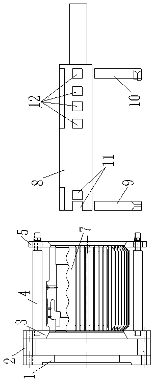
[0017] Embodiment 1: with reference to attached figure 1 , 2 . A faceplate-type tooling for machine base finishing, which includes a bedside connecting plate 1, a positioning plate 3, a connecting column 2, a faceplate connecting rod 4, a faceplate pressing plate 5, and a tool bar 8 installed on a tool holder; the bedside connecting plate 1 is fixedly connected to the main shaft of the machine tool; the positioning plate 3 and the faceplate pressure plate 5 are set parallel to the bedside connecting plate 1, and there are three connecting columns 2 arranged between the bedside connecting plate 1 and the positioning plate 3, and the three connecting columns 2 are close to the bedside The edge of the disk 1 is connected, and the three connecting columns 2 are arranged evenly, that is, the angle between the three connecting columns 2 is 120 degrees; the length of the connecting columns 2 is 50-80mm, and connecting bolts are arranged in the connecting columns 2 , through connect...

Embodiment 2

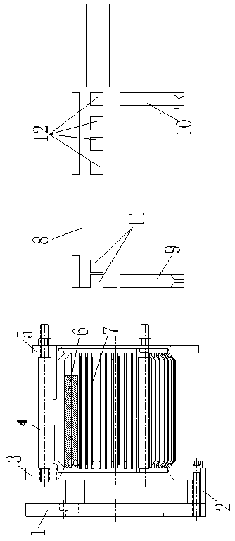
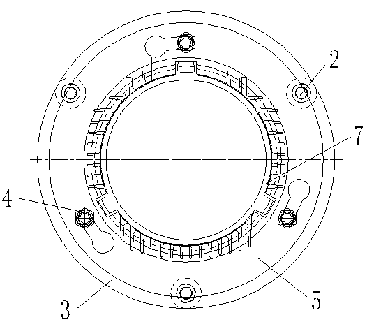
[0018] Embodiment 2: on the basis of embodiment 1, with reference to appended image 3 , 4 . A faceplate-type tooling for fine-turning machine bases, two machine base support rods 6 are arranged between the positioning plate 3 and the faceplate pressure plate 5, and one end of the machine base support rods 6 is fixed on the positioning plate 3; When the machine base is used, the support rod 6 of the machine base is closely fixed on the outer diameter side of the workpiece 7, and the outer diameter will be used for positioning, and the external heat dissipation ribs will be pressed axially. Improve the quality of workpiece processing.


PUM


Abstract

The invention relates to a faceplate-type tool used for motor base fine turning. The faceplate-type tool used for motor base fine turning comprises a machine head connecting disk and a cutter bar installed on a cutter post. The outer side of the machine head connecting disk is provided with a locating plate parallel to the machine head connecting disk. A plurality of uniformly distributed connecting pillars are arranged between the machine head connecting disk and the locating plate, and the other side of the locating plate is provided with a faceplate pressing plate parallel to the locating plate. The locating plate and the faceplate pressing plate are connected with each other through a plurality of uniformly distributed faceplate connecting bars. The middle of the locating plate and the middle of the faceplate pressing plate are both provided with coaxial locating through holes. Two cutter grooves are formed in the front end of the cutter bar. An inner hole cutter and a plane cutter are installed in the cutter grooves respectively. A plurality of cutter grooves are formed in the rear end of the cutter bar, and a plane cutter is installed in one of the cutter grooves. Compared with the background technology, the faceplate-type tool used for motor base fine turning is adopted, so that the operation of two times of clamping is changed into the operation of one time of clamping and one time of turning without the need for turning round a clamping workpiece or changing the cutter or transforming processes. The coaxiality and end face parallelism degree of a motor base are assured effectively; auxiliary time is shortened effectively, and machining efficiency and benefit are improved greatly.

Description

technical field [0001] The invention relates to a tooling fixture for turning, in particular to a tooling fixture installed on a lathe for finishing the motor frame, and belongs to the technical field of tooling for turning. Background technique [0002] When machining the motor frame, the coaxiality of the inner circle and seam at both ends is very high. Usually, the machine base needs to be turned around and turned during processing, that is, the plane of the non-outlet end of the machine base, the seam and the neutral gear are turned first, and the holes are drilled and the threads are tapped; , neutral gear, and iron core gear, but such a machine base needs to be converted to four processes after turning, which is time-consuming and laborious, and it is difficult to ensure the coaxiality and runout of each clamping process, and the machining accuracy is low. [0003] CN104625612A discloses a processing method for a small and medium-sized motor frame, in which the iron c...

Claims


Application Information

Patent Timeline
Patent Type & Authority Patents(China)
IPC IPC(8): B23Q3/12B23B29/26
CPCB23B29/26B23Q3/12
Inventor 徐晨丽
Owner HANGZHOU JIANGCHAO ELECTRICAL MACHINERY
Why Eureka
Try Eureka