
A pneumatic clamping and rotating device

A rotating device, pneumatic technology, applied in the field of robots to ensure reliability and stability, improve rotating efficiency, and achieve fast rotating speed.

Active Publication Date: 2016-11-23
HARBIN ENG UNIV
View PDF6 Cites 0 Cited by
  • Summary
  • Abstract
  • Description
  • Claims
  • Application Information

AI Technical Summary

Problems solved by technology

The realization of these actions is realized by complex devices

Method used


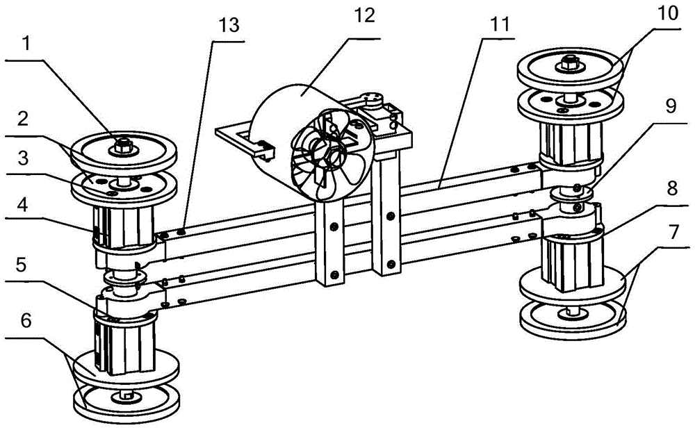
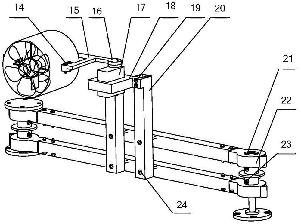
Image

  • A pneumatic clamping and rotating device
  • A pneumatic clamping and rotating device
  • A pneumatic clamping and rotating device

Examples


Embodiment Construction

[0015] The present invention is described in more detail below in conjunction with accompanying drawing example:

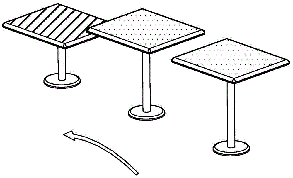
[0016] combine Figure 1~4 , the object of the present invention is to provide a pneumatic clamping and rotating device, which can move and rotate between platforms, expand the application range of the robot, and solve the problem of poor stability of the previous clamping mechanism, slow speed of the rotating mechanism, and inability to apply to different heights, etc. Problem, the present invention provides a device with simple structure and high clamping and turning efficiency.

[0017] The pneumatic clamping and rotating device is mainly composed of clamping disc, cylinder, flange, connecting shaft, ducted fan, steering gear, rolling bearing, connecting block, bracket and so on. In the specific embodiment, the frame is the main supporting part, the four groups of cylinders are the power source for clamping the disc, the ducted fan is the power source for the ...


PUM


Abstract

The invention aims at providing a pneumatic clamping rotating device. The pneumatic clamping rotating device comprises a rack, a clamping mechanism and a rotating mechanism, wherein the rack comprises a first cross beam and a second cross beam, a first connecting block and a fourth connecting block are respectively mounted at the two ends of the first cross beam, a second connecting block and a third connecting block are respectively mounted at the two ends of the second cross beam, the clamping mechanism comprises a first clamping unit, a second clamping unit, a third clamping unit and a fourth clamping unit, which have the same structure, the rotating mechanism comprises a ducted fan, a steering engine and a rotating bracket, the ducted fan is connected with an output shaft of the steering engine through a ducted fan base, the steering engine is fixed to a steering engine base, the steering engine base is fixed to the rotating bracket, and the rotating bracket is fixedly connected with the first cross beam and the second cross beam. The pneumatic clamping rotating device can move and rotate between platforms, broaden the application range of a robot and solve the problems that the original clamping mechanism is poor in stability, low in rotating mechanism speed, incapable of adapting to different heights and the like.

Description

technical field [0001] The invention relates to a robot, in particular a robot that moves and rotates between platforms. Background technique [0002] Robot is a kind of automatic equipment with strong adaptability and flexibility, and it is an important invention of human beings in the 20th century. With the rapid development of science and technology and the acceleration of people's modern life rhythm, robots have entered the field of people's life, providing convenient services for modern life, not only bringing convenience to human life, but also improving efficiency. For example, nanny robots produced in the United States can tell stories, play songs, switch televisions, and bathe children. When the baby goes to bed, it cleans the room and does other housework. In the event of an accident, it will also call in time to notify parents who go to work or go out. The United States has also produced a robot that helps housewives with housework. This kind of robot can do v...

Claims


Application Information

Patent Timeline
Patent Type & Authority Patents(China)
IPC IPC(8): B25J19/00B25J9/14
Inventor 王茁黄新禹王涛张波单雪李思宇李宁谢敏燕蔡明智王大欢傅质斌李文琦
Owner HARBIN ENG UNIV
Learn More