Double-column rotary corrosive-wear testing machine

A rotating, double-column technology, used in weather resistance/light resistance/corrosion resistance, wear resistance testing, measuring devices, etc., can solve the problems of uneven medium, limited medium composition, large particle size, etc., to ensure stability Effect

Active Publication Date: 2016-07-27
BAOSHAN IRON & STEEL CO LTD
View PDF13 Cites 22 Cited by
  • Summary
  • Abstract
  • Description
  • Claims
  • Application Information

AI Technical Summary

Problems solved by technology

[0015] The purpose of the present invention is to provide a double-column rotary corrosion and wear testing machine, which can test the abrasive performance of materials in a multiphase flow medium, and overcome the difficulties in the prior art that it is difficult to perform electrochemical tests, limited medium components, uneven medium and inability to Analysis of problems such as corrosion, wear and their interaction, the content of solid particles in the medium can be adjusted arbitrarily and the particle size is large (up to 1-10mm)

Method used


Image

  • Double-column rotary corrosive-wear testing machine
  • Double-column rotary corrosive-wear testing machine
  • Double-column rotary corrosive-wear testing machine

Examples


Embodiment Construction

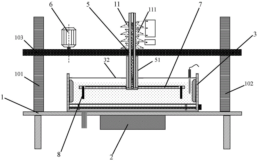
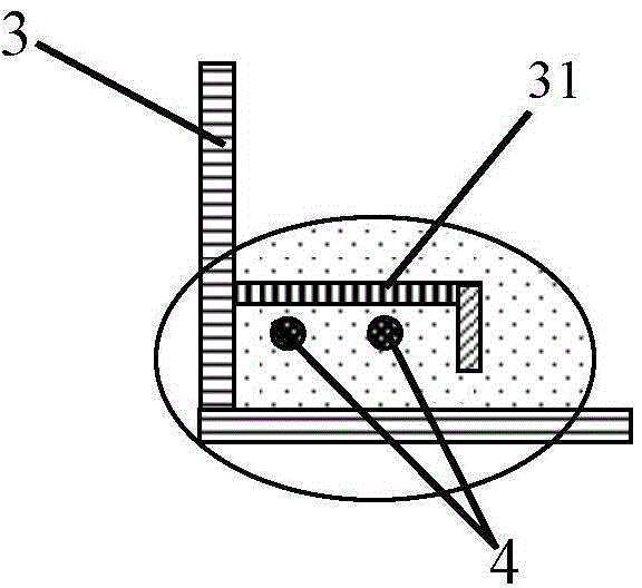
[0050] see Figure 1 to Figure 6 , the double-column rotary abrasion testing machine of the present invention, it comprises, test bench 1, two upright columns 101,102 are set on both sides of the upper end surface, a beam 103 is set on the top of the upright column, and a through hole is set in the center of the beam 103; the beam lifting drive mechanism 2, Set on the test bench 1, connect the crossbeam 103, the crossbeam 103 moves up and down along the columns 101, 102; the test tube 3 is set in the center of the upper end surface of the test bench 1, and the inner and lower part of the test tube 3 is provided with an annular temperature control pipe 4. A pipe cover plate 31 connected to the inner wall of the test cylinder 3 is provided above the temperature control pipeline 4; a cover plate 32 with a central hole is provided at the upper end of the test cylinder 3; the transmission shaft 5 is vertically installed on the test bench 1 In the central through hole of the crossbe...


PUM


Abstract

The invention provides a double-column rotary corrosive-wear testing machine, comprising a testing stand, which is provided with two columns, wherein a crossbeam is arranged on the columns and a through hole is formed in the center of the crossbeam; a crossbeam elevating and driving mechanism, which is arranged on the test stand and connected with the crossbeam; a testing drum, which is arranged on the center of the test stand, wherein an annular temperature control/cooling pipeline is arranged in the lower part of the testing drum; a transmission shaft, which passes through and is arranged in the through hole in the crossbeam; a sample clamping disc, which is fixed at the lower end of the transmission shaft, wherein the upper end surface of the sample clamping disc is provided with an annular groove, and the outer sides of the annular groove are provided with installation through holes; working electrodes, i.e., to-be-tested samples, which are inserted into the installation through holes; an auxiliary electrode, i.e., an annular platinum wire, which is arranged in the annular groove of the sample clamping disc; reference electrodes, which are uniformly distributed on the sample clamping disc at positions corresponding to the working electrodes; and a dynamic connection pool, which comprises annular dovetail cups, wherein the annular dovetail cups sleeve the upper part of the transmission shaft, leading-out circular rings are arranged at the bottom of the inner sides of the annular dovetail cups, the outer sides of the leading-out circular rings are provided with wiring copper columns penetrating the bottoms of the cups, the interior of each annular dovetail cup is provided with an electric needle, the lower ends of the electric needles are certain distance away from the leading-out circular rings, and the working electrodes, the auxiliary electrode and the reference electrodes are connected with the dynamic connection pool through leads.

Description

technical field [0001] The invention relates to corrosion and wear testing equipment, in particular to a double-column rotary corrosion and wear testing machine capable of accurately measuring and evaluating the corrosion resistance and wear performance of various materials in a corrosive environment. Background technique [0002] Erosion generally refers to the existence of corrosion while wear occurs, and mostly occurs in the environment of multiphase flow media. In the process of dredging channels and land reclamation, engineering equipment such as dredgers and sand dredgers transport a large amount of sediment to the land through pipelines, and the two-phase flow medium mixed with solid and liquid has obvious abrasion on the inner wall of the pipeline during the movement. destroy. During the working process, the solid particles in the slurry scratch and collide with the inner wall of the pipeline at a high speed, causing pipeline wear; at the same time, seawater itself ...

Claims


Application Information

Patent Timeline
Patent Type & Authority Applications(China)
IPC IPC(8): G01N17/02G01N3/56
Inventor 宋凤明胡晓萍李建业
Owner BAOSHAN IRON & STEEL CO LTD
Why Eureka
Try Eureka