Supporting module for fused deposition modeling three-dimensional printing and generating method of supporting module

A supporting module and 3D printing technology, applied in the direction of additive processing, etc., can solve the problem that the supporting module 1 is difficult to remove, and achieve the effect of reducing the difficulty of dismantling

Inactive Publication Date: 2015-11-18
PANOWIN TECH
View PDF4 Cites 26 Cited by
  • Summary
  • Abstract
  • Description
  • Claims
  • Application Information

AI Technical Summary

Problems solved by technology

However, due to errors in the actual printing process, such as figure 2 As shown, the upper surface a of the support module 1' and the lower surface b of the suspended part 21' will be uneven, and the adhesion of individual points between the surfaces will occur. The number of adhesion points 3' directly determines the support module 1'. The degree of adhesion to the model 2', the more adhesion points 3', the more difficult it is to remove the support module 1'

Method used


Image

  • Supporting module for fused deposition modeling three-dimensional printing and generating method of supporting module
  • Supporting module for fused deposition modeling three-dimensional printing and generating method of supporting module
  • Supporting module for fused deposition modeling three-dimensional printing and generating method of supporting module

Examples


no. 1 example

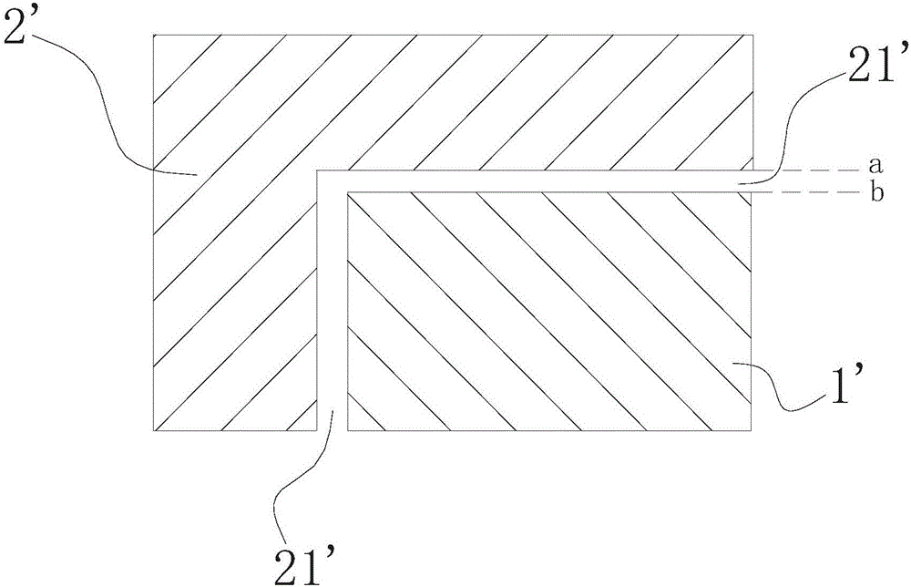
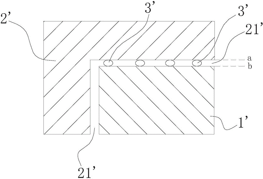
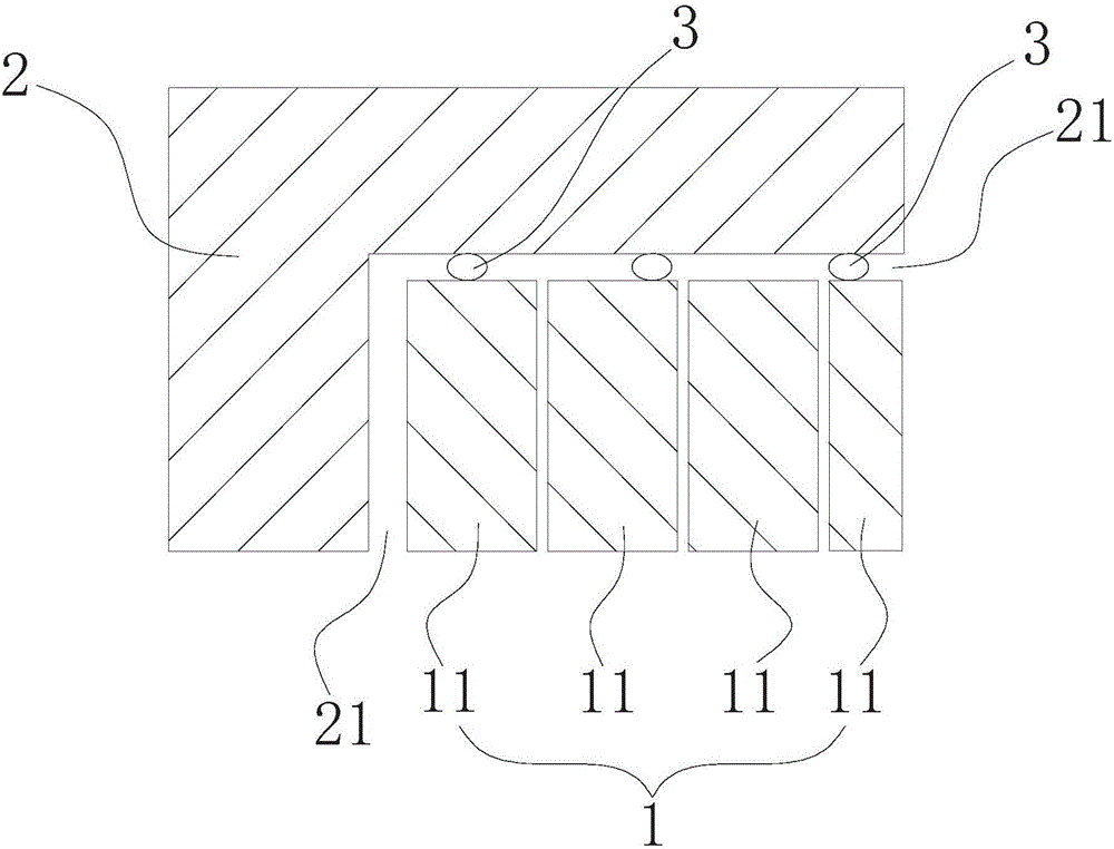
[0038] See image 3 with Figure 4 , which respectively show the support module of the fusion deposition molding 3D printing and the longitudinal sectional view of the model after printing and the cross-sectional view of the support module according to the first embodiment of the present invention. Model 2 has one or more overhangs. The supporting module 1 is arranged in a suspended part of the model 2 . image 3 Take a suspended part 21 of model 2 as an example for illustration. The support module 1 is arranged under the suspended part 21 of the model 2, and is used to provide multiple fixing points for the suspended part 21 during the process of printing the model 2 to support the suspended part 21. After the printing is completed, the support module 1 is removed from the model 2 The lower part of the floating part 21 is removed. exist image 3 with Figure 4In the shown embodiment, the suspended part whose vertical projection profile is rectangular and horizontal proj...

no. 2 example

[0053] See Figure 9 with Figure 10 , which respectively show the cross-sectional view of the support module of fusion deposition molding 3D printing according to the second embodiment of the present invention and the cross-sectional view of the array before the intersection of the array and the suspended part during the printing process. with the above Figure 4 The difference in the first embodiment shown in is that, as Figure 9 As shown, the supporting units 11 are arranged in a matrix, and the cross-section of each central supporting unit 112 is rectangular. Furthermore, in order to achieve the above Figure 9 The cross-section of the support module 1 is shown. In this embodiment, before the intersection of the array 12 and the suspended part 21, the cross-section of each support unit 11 is rectangular, and the support units 11 are arranged in a matrix, as shown in Figure 10 shown. This embodiment can also be implemented and will not be repeated here.

no. 3 example

[0055] See Figure 11 with Figure 12 , which respectively show the cross-sectional view of the support module of the fusion deposition molding 3D printing according to the third embodiment of the present invention and the cross-sectional view of the array before the intersection of the array and the suspended part during the printing process. with the above Figure 4 The difference in the first embodiment shown in is that, as Figure 11 As shown, the adjacent supporting units 11 are alternately arranged in front and back, and the cross-section of each central supporting unit 112 is triangular. Among them, the setting of positive and negative phases (refer to Figure 12 ) means that each support unit 11 with a triangular cross-section is in the opposite shape of its adjacent support units 11 up and down or left and right in the same plane. Taking a triangular cross-section of a support unit 11 as an example, it rotates 180° with the center of the triangle The triangle form...


PUM


Abstract

The invention discloses a supporting module for fused deposition modeling three-dimensional printing and a generating method of the supporting module. The supporting module is used for supporting the suspended portion of a model needing three-dimensional printing. The supporting module comprises multiple supporting units arranged at intervals to provide multiple fixation points for the suspended portion. Compared with an original supporting module, the supporting module can be more easily removed from the suspended portion of the model while the supporting performance is kept.

Description

technical field [0001] The invention relates to the field of fusion deposition modeling three-dimensional printing (FDM), in particular to a support module for fusion deposition modeling three-dimensional printing, a generation method thereof, and a three-dimensional printing method for a printed model using the support module. Background technique [0002] Fusion deposition modeling three-dimensional printing (FDM) technology means that after the printing material is heated to a temperature exceeding the melting point of the material, the material melts into a viscous semi-liquid state. The printing material is extruded through the nozzle, and after touching the platform or the previously printed material, it cools down and solidifies to form a solid layer. Under the control of the program, this process is repeated, and the solid structure of the required three-dimensional model is stacked layer by layer. [0003] Due to the characteristics of fusion deposition modeling 3D...

Claims


Application Information

Patent Timeline
Patent Type & Authority Applications(China)
IPC IPC(8): B29C67/00B33Y30/00B33Y10/00
Inventor 潘敬华刘海川季明林进发
Owner PANOWIN TECH
Why Eureka
Try Eureka