Front axle wheel end structure and automobile

A wheel end and front axle technology, which is applied in the front axle wheel end structure and the automotive field, can solve problems such as cumbersome procedures, reduced safety and reliability performance, and shortened service life, so as to achieve simple disassembly and maintenance processes, save maintenance man-hours, and ensure normal operation The effect of force

Inactive Publication Date: 2015-11-18
ANHUI JIANGHUAI AUTOMOBILE GRP CORP LTD
View PDF8 Cites 3 Cited by
  • Summary
  • Abstract
  • Description
  • Claims
  • Application Information

AI Technical Summary

Problems solved by technology

[0004] Due to the structure of the wheel hub 101 and the brake disc 103 in the existing front axle wheel end structure, the replacement of the brake disc 103 needs to be completely disassembled and then reassembled. The process is cumbersome, time-consuming and laborious, resulting in low maintenance efficiency. Increase the cost of replacement; at the same time, because the ABS ring gear is installed on the hub 101 by hot pressing, it is difficult to disassemble, and after disassembly and assembly, the cylindricity of the ABS ring gear is damaged and it is difficult to restore, which may easily lead to ABS signal Abnormal; and the bearing needs to be disassembled many times during the life cycle, causing early damage to the bearing and shortening its service life, and the disassembly, assembly and adjustment of the bearing must be completed through professional tooling equipment. The maintenance and replacement of the brake disc at the station will affect the stress state of the bearing, which will cause it to be unable to be in a normal state during operation, especially if the bearing clearance is not adjusted properly, which will cause serious early fatigue of the bearing and shorten its service life. The safety and reliability performance of the whole vehicle is reduced

Method used


Image

  • Front axle wheel end structure and automobile
  • Front axle wheel end structure and automobile

Examples


Embodiment Construction

[0026] In order to make the object, technical solution and advantages of the present invention clearer, the present invention will be further described in detail below in conjunction with the accompanying drawings and embodiments. It should be understood that the specific embodiments described here are only used to explain the present invention, not to limit the present invention.

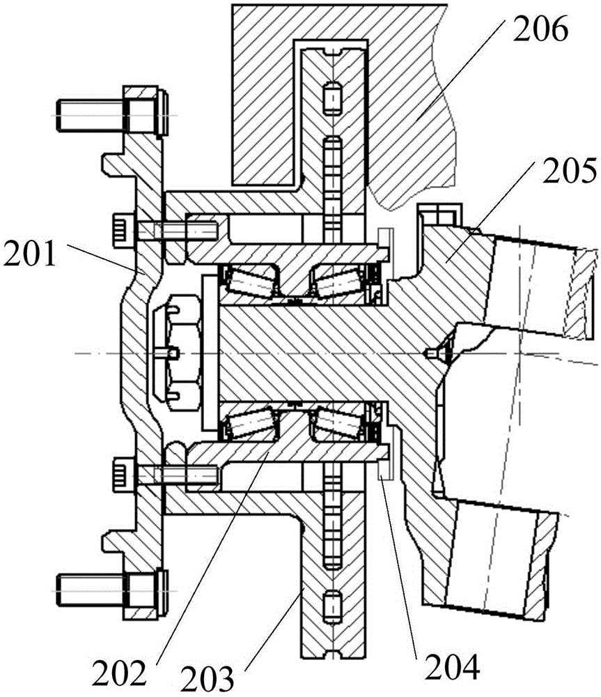
[0027] Please refer to figure 2 , in a specific embodiment, the front axle wheel end structure provided by the present invention includes a hub 202 and a brake disc 203, the brake disc 203 is provided with a hub hole; the hub 202 is a stepped shaft, and the stepped shaft is provided with an axial The through bearing hole; the large shaft end of the stepped shaft is inserted into the hub hole, and locked with the brake disc 203 through the locking mechanism; the disc body of the brake disc 203 is located at the small shaft end of the stepped shaft; the steering knuckle passes through the bearing R...


PUM


Abstract

The invention belongs to the technical field of automobile components, and provides a front axle wheel end structure and an automobile. The front axle wheel end structure comprises a hub and a brake disc. The brake disc is provided with a hub hole. The hub is a stepped shaft which is provided with an axially-through bearing hole. The large shaft end of the stepped shaft is inserted in the hub hole and locked to the brake disc through a locking mechanism. A disc body of the brake disc is located at the small shaft end of the stepped shaft. A knuckle is rotationally installed in the bearing hole through a bearing. According to the front axle wheel end structure, due to the fact that the hub hole is formed in the brake disc and the hub is inserted into the hub hole and locked by the locking mechanism, when the brake disc becomes invalid and needs to be replaced, the brake disc can be disassembled only by disassembling a tire at first, then disassembling a brake caliper and loosening the locking mechanism; the disassembly and assembly technology is simple, maintenance time is shortened, maintenance efficiency is improved, and the brake disc placement cost is reduced; due to the fact that an ABS gear ring and the bearing do not need to be disassembled, the ABS gear ring and the bearing are protected, normal stress of the bearing is ensured, and the service life of the bearing is prolonged.

Description

technical field [0001] The invention belongs to the technical field of automobile parts, and in particular relates to a front axle wheel end structure and an automobile. Background technique [0002] The wheel end structure of the front axle is an important part of the car, and its structure is as follows: figure 1 As shown, one end of the hub 101 is provided with a flange, the other end is provided with a tapered shaft, and a through hole is provided in the center, which runs through the entire flange and the tapered shaft; the outer wall of the tapered shaft is inserted with a brake disc 103, and through the flange Axially limited with the brake disc 103, and locked by bolts; one end of the tapered shaft inserted into the brake disc 103 is also inserted with an ABS (antilockbrakesystem, anti-lock brake system) ring gear; the through hole is connected through the bearing rotation The steering knuckle 104, and the shaft end of the steering knuckle 104 locks the bearing, the...

Claims


Application Information

Patent Timeline
Patent Type & Authority Applications(China)
IPC IPC(8): B60B27/00
Inventor 于建蕾郭春雷王定华王俊伟
Owner ANHUI JIANGHUAI AUTOMOBILE GRP CORP LTD
Why Eureka
Try Eureka