Kerb drainage system and kerb drainage method for transformer substation

A technology for drainage systems and substations, applied in waterway systems, sewer systems, water supply devices, etc., can solve problems such as inconvenient blockage, increased engineering volume, and land occupation, so as to reduce the possibility of water accumulation and reduce the occupied area , the effect of reducing workload

Inactive Publication Date: 2015-11-18
DONGYING POWER SUPPLY COMPANY STATE GRID SHANDONG ELECTRIC POWER +1
View PDF0 Cites 2 Cited by
  • Summary
  • Abstract
  • Description
  • Claims
  • Application Information

AI Technical Summary

Problems solved by technology

The substation drainage system usually adopts the form of underground underground pipes, which not only occupies land, but also increases the excavation workload of the construction unit and is inconvenient to repair due to problems such as blockage. labor intensity, and it is necessary to set specific drainage ditches, resulting in an increase in the amount of work and seriously affecting the construction effect

Method used


Image

  • Kerb drainage system and kerb drainage method for transformer substation
  • Kerb drainage system and kerb drainage method for transformer substation
  • Kerb drainage system and kerb drainage method for transformer substation

Examples


Embodiment Construction

[0017] combined with Figure 1-3 , to further describe the present invention:

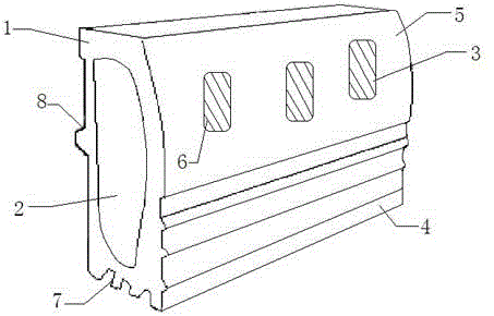
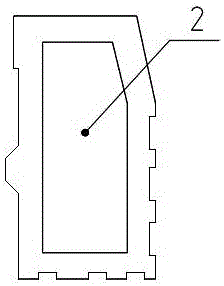
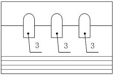
[0018] The curb drainage system for substations mentioned in the present invention includes a base body 1, the base body 1 is made of resin concrete, a plurality of base bodies 1 are connected end to end in sequence, and the front end surface of the base body 1 is connected to the top of the base body 1 through an arc-shaped connecting body 5, The arc-shaped connecting body 5 is provided with three water inlet holes 3, and the inner middle of the base body 1 is horizontally provided with a drainage channel 2, and the water inlet holes 3 are connected to the drainage channel 2, and the water inlet holes 3 are A filter screen 6 is provided. One end of the base 1 is provided with a bayonet, and the other end of the base 1 is provided with a slot. When the two bases are connected, they are connected through the bayonet and the slot.

[0019] Among them, the back of the base 1 is provided with a fixed ...


PUM


Abstract

The invention relates to a kerb drainage system and a kerb drainage method for a transformer substation. According to the technical scheme, the kerb drainage system comprises a plurality of base bodies, wherein the base bodies consist of resin concrete, and are sequentially connected to one another end to end; the front end surface of each base body is connected with the top of the base body through an arc-shaped connector; each arc-shaped connector is provided with three water feeding holes; drainage channels are horizontally formed in middles of the insides of the base bodies; the water inlet holes are connected with the drainage channels; each water inlet hole is provided with a filtering net; one end of each base body is provided with a bayonet; the other end of each base body is provided with a slot; and each two base bodies are connected with each other by matching the corresponding bayonet and the corresponding slot. The kerb drainage system can be built while kerb is built, workload of a construction unit is reduced, excavation frequency is reduced, occupied area is also reduced, rainwater can be drained out of the transformer substation as soon as possible, and possibility of ponding of the transformer substation is reduced.

Description

technical field [0001] The invention relates to a drainage system for a substation, in particular to a curb drainage system and method for a substation. Background technique [0002] Currently, curbs and drainage systems are integral and separate parts of substations. The substation drainage system usually adopts the form of underground underground pipes, which not only occupies land, but also increases the excavation workload of the construction unit and is inconvenient for maintenance due to problems such as blockage. The labor intensity is high, and specific drainage ditches need to be set, which leads to an increase in the amount of work and seriously affects the construction effect. Contents of the invention [0003] The purpose of the present invention is to provide a curb drainage system and method for substations in view of the above-mentioned defects in the prior art, which is convenient for construction, saves time and effort, and improves work efficiency. [0...

Claims


Application Information

Patent Timeline
Patent Type & Authority Applications(China)
IPC IPC(8): E03F3/04
Inventor 张武谷晓彩初明坤解云兴刘囡
Owner DONGYING POWER SUPPLY COMPANY STATE GRID SHANDONG ELECTRIC POWER
Why Eureka
Try Eureka