Liquid collector

A confluence device and liquid technology, applied in the field of oil displacement, can solve problems such as viscosity loss

Inactive Publication Date: 2015-11-18
胡显三
View PDF3 Cites 0 Cited by
  • Summary
  • Abstract
  • Description
  • Claims
  • Application Information

AI Technical Summary

Problems solved by technology

[0005] In the liquid confluence device in the prior art, since the intersection of the injection water input pipe and the polymer input pipe is at a right angle, this results in a vertical flow between the polymer solution and the injection water.
Furthermore, when the injection water passes through the junction, a shearing force is formed on the polymer solution downward along the axis of the injection water input pipe, and the shearing force will cause the viscosity of the polymer solution to be reduced when the injection water and the polymer solution are mixed. lost in the process

Method used


Image

  • Liquid collector

Examples


Embodiment Construction

[0016] In order to enable those skilled in the art to better understand the technical solutions in the present application, the technical solutions in the embodiments of the present application will be clearly and completely described below in conjunction with the drawings in the embodiments of the present application. Obviously, the described The embodiments are only some of the embodiments of the present application, but not all of them. Based on the embodiments in this application, all other embodiments obtained by persons of ordinary skill in the art without making creative efforts shall fall within the protection scope of the present invention.

[0017] Embodiments of the present invention will be described below in conjunction with the accompanying drawings.

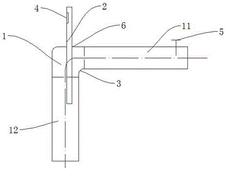
[0018] figure 1 It is a structural schematic diagram of a liquid confluence device of the present invention. Such as figure 1 As shown, a liquid confluence device proposed by the present invention includes a fir...


PUM


Abstract

The invention discloses a liquid collector, comprising a first pipe and a second pipe. The first pipe is used for bearing a first liquid and comprises a liquid incoming pipe and a liquid outgoing pipe integrally made; the axis of the liquid incoming pipe is perpendicular to that of the liquid outgoing pipe; the liquid incoming pipe is connected with the liquid outgoing pipe through a bend; the upper wall of a part, close to the bend, of the liquid incoming pipe is provided with a through hole; the second pipe is used for bearing a second liquid; the outer diameter of the second pipe is equal to the diameter of the through hole; the second pipe penetrates the through hole and extends into the liquid outgoing pipe of the first pipe; the axis of the second pipe is parallel to that of the liquid outgoing pipe. The liquid collector is effective in decreasing viscosity loss of a polymer solution during a mixing process of injected water and the polymer solution.

Description

technical field [0001] The invention relates to the field of oil displacement, in particular to a liquid confluence device. Background technique [0002] At present, oil production in oilfields generally adopts the method of coordinating injection wells and production wells. In injection well oil production, it is generally necessary to inject injection water into the oil layer, and through the driving effect of the injected water on the oil in the oil layer, the oil can be produced in the oil production well. [0003] Viscosity is a physical property of a fluid used to measure the viscosity of a fluid. If there is relative motion between the object and the fluid, a frictional force will be generated between the object and the fluid due to fluid viscosity, and the frictional force is used to prevent the relative motion between the object and the fluid. [0004] Due to the low viscosity of the injected water itself, furthermore, the frictional force generated after the inje...

Claims


Application Information

Patent Timeline
Patent Type & Authority Applications(China)
IPC IPC(8): E21B43/20
Inventor 胡显三
Owner 胡显三
Why Eureka
Try Eureka