Device and method for measuring pressure surface angle of dovetail-type blade tenon

An angle measurement device and blade tenon technology, which is applied in angle/taper measurement and other directions, can solve the problems that the actual value cannot be obtained, and achieve the effects of accurate and convenient measurement, accurate measurement results, and precise displacement transmission

Active Publication Date: 2015-11-18
AECC AVIATION POWER CO LTD
View PDF4 Cites 14 Cited by
  • Summary
  • Abstract
  • Description
  • Claims
  • Application Information

AI Technical Summary

Problems solved by technology

When testing the tenon of dovetail blades, there are generally two measurement methods. The first one is to detect a single element of the tenon, which includes the width of the dovetail node, the angle of the dovetail, and the straightness of the dovetail. This detection method directly measures the measured The actual value of the size; the second is to check the tenon comprehensive elements, which includes projection inspection, tenon comprehensive gauge inspection, etc., among which the projection inspection is to project the two pressure surfaces, and the tenon comprehensive gauge is measured by two measures, one large and one small. The qualified tenon can be snapped in, so these testing methods can only judge whether the comprehensive size of the tenon is qualified, and cannot get the actual value

Method used


Image

  • Device and method for measuring pressure surface angle of dovetail-type blade tenon
  • Device and method for measuring pressure surface angle of dovetail-type blade tenon
  • Device and method for measuring pressure surface angle of dovetail-type blade tenon

Examples


Embodiment Construction

[0031] The present invention will be described in further detail below in conjunction with the accompanying drawings.

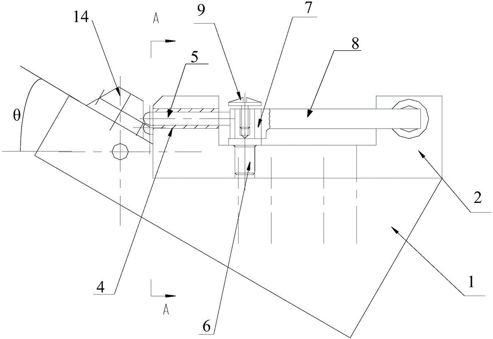
[0032] In the present invention, when the positioning block 2 is placed horizontally, the short-axis end face of the lever 8 faces the front side, and the long-axis end face faces the right side, which is only for clarity of description, rather than limitation of the present invention.

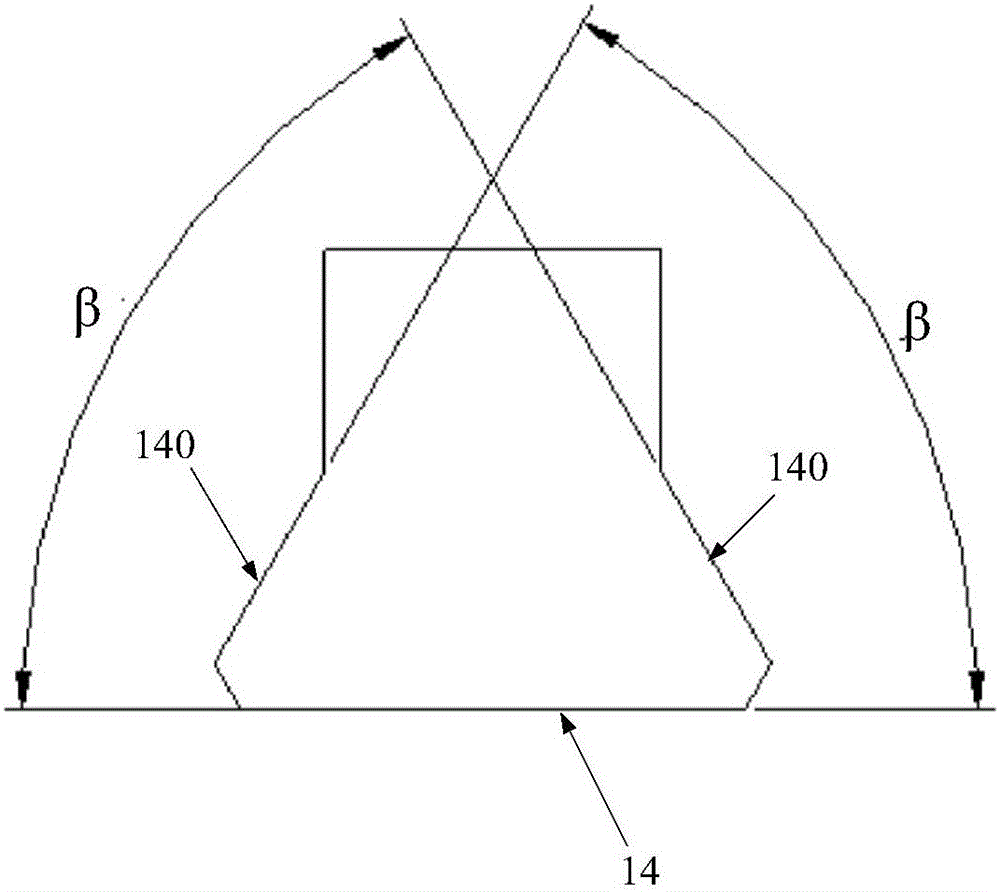
[0033] see figure 1 , the present invention adopts a standard part 14 of the dovetail blade tenon to be tested, the standard part 14 is consistent with the shape of the dovetail blade tenon to be tested, and only the actual value of the angle β of the pressure surface 140 is slightly different, wherein the dovetail blade tenon to be tested The value of the pressure surface angle β is 60°±4′, and the pressure surface angle β of the standard part 14 is considered to be equal to 60° in the present invention, and its error is ignored.

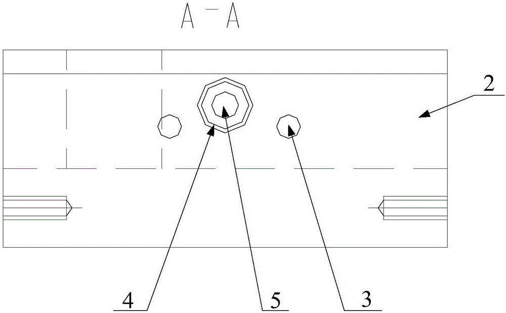
[0034] see Figure 2 to Figure 4 , the pr...


PUM


Abstract

The invention relates to a device and a method for measuring a pressure surface angle of a dovetail-type blade tenon. The device comprises a base on which a positioning block is mounted. The base is provided with an oblique surface. The oblique surface is attached to the left end surface of the positioning block, thereby forming an acute-angle area. The positioning block is provided with a dial gauge and a slidable movable measuring pin, wherein the dial gauge and the slidable movable measuring pin are horizontal. The movable measuring pin is vertical with the left end surface of the positioning block. Furthermore the left end of the movable measuring pin extends into the acute-angle area, and the right end is connected with a lever which can rotate around a fixed shaft for transmitting the displacement of the movable measuring pin to the measuring head of the dial gauge. Below the movable measuring pin, two positioning pins are fixedly mounted at the left end of the positioning block. The end of each positioning pin is aligned with the end of the movable measuring pin. According to the device and the method, the pressure surface of a standard component or the tenon to be measured pushes the movable measuring pin to slide. Displacement is transmitted to the dial gauge through the lever. An angle difference of the pressure surface angle of the tenon relative to the standard component is obtained through direct measurement. The accurate value of the pressure surface angle is obtained through calculation, and convenient and accurate measurement is realized.

Description

【Technical field】 [0001] The invention belongs to the measurement technology of aero-engines, and in particular relates to a device and method for measuring the pressure surface angle of a tenon of a dovetail blade. 【Background technique】 [0002] Blades are a very important type of aero-engine parts and play a key role in the performance of the engine. The angle of the pressure surface is required to be 60°±4’, and its actual value needs to be tested. When testing the tenon of dovetail blades, there are generally two measurement methods. The first one is to detect a single element of the tenon, which includes the width of the dovetail node, the angle of the dovetail, and the straightness of the dovetail. This detection method directly measures the measured The actual value of the size; the second is to check the tenon comprehensive elements, which includes projection inspection, tenon comprehensive gauge inspection, etc., among which the projection inspection is to project...

Claims


Application Information

Patent Timeline
Patent Type & Authority Applications(China)
IPC IPC(8): G01B5/24
Inventor 吉建新牛阿妮陶彩玲冯朝生陈勇罗雄狮
Owner AECC AVIATION POWER CO LTD
Why Eureka
Try Eureka