Anti-blocking burner

A burner and anti-blocking technology, applied in the direction of burner, burner, burner ignition device, etc., can solve the problems of overflow blockage and difficult cleaning

Pending Publication Date: 2019-07-12
NINGBO FOTILE KITCHEN WARE CO LTD
View PDF1 Cites 0 Cited by
  • Summary
  • Abstract
  • Description
  • Claims
  • Application Information

AI Technical Summary

Problems solved by technology

The existing ignition hole is generally small hole structure, which is easy to be blocked by overflow liquid and difficult to clean

Method used


Image

  • Anti-blocking burner
  • Anti-blocking burner
  • Anti-blocking burner

Examples


Embodiment Construction

[0034] The present invention will be further described in detail below in conjunction with the accompanying drawings and embodiments.

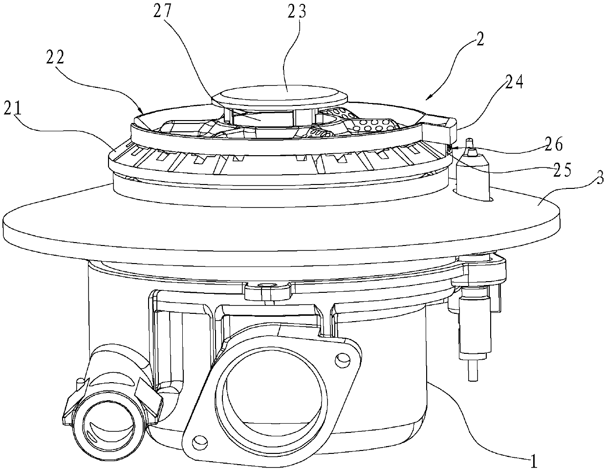
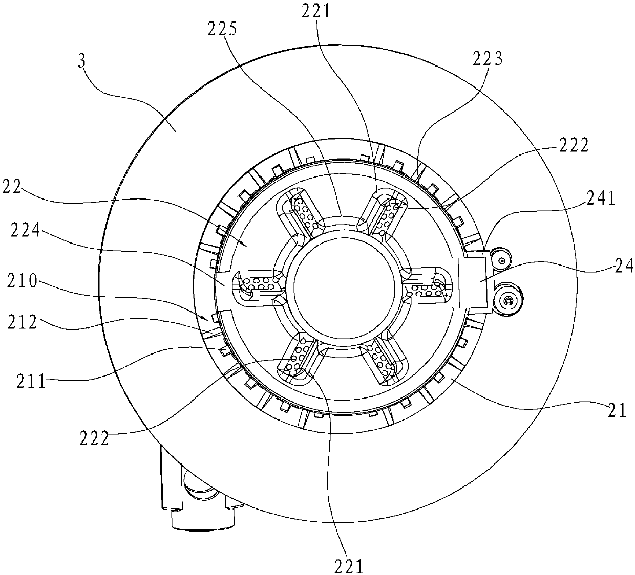
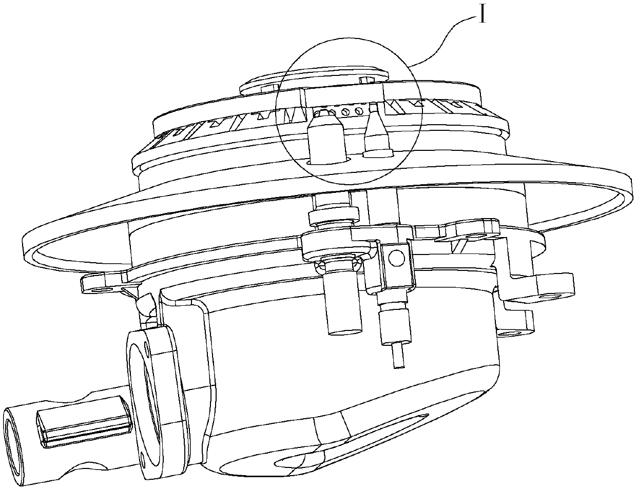
[0035] Such as Figure 1-12 As shown, an anti-blocking burner includes a base 1 on which a first cavity 11 and a second cavity 12 opening upwards are formed, and the second cavity 12 is arranged around the first cavity The outer periphery of the body 11, the two share the partition ring wall 14. The upper cover of the first cavity 11 is provided with a fire cover 2, and the fire cover 2 includes an outer ring fire cover 21 with a peripheral wall and an inner ring fire cover 22, and the above-mentioned inner ring fire cover 22 is circular and is set on the above-mentioned outer ring. The top of the fire cover 21, and the inner ring fire cover 22 and the outer ring fire cover 21 surround the air mixing chamber 20. The outer ring fire cover 21 is provided with an ignition hole 26, and one side of the inner ring fire cover 22 is integrally forme...


PUM


Abstract

The invention relates to an anti-blocking burner. The anti-blocking burner comprises a pedestal. A first cavity which is opened upwards is formed in the pedestal. A burner cap is arranged on the firstcavity in a covering mode and further comprises an outer ring burner cap body with a circumferential wall and an inner ring burner cap body with a circumferential wall. The inner ring burner cap bodyis circular and further covered at the top of the outer ring burner cap body, and the inner ring burner cap body and the outer ring burner cap body are encircled to form a gas mixing cavity. An ignition hole is formed in the outer ring burner cap body. A spill-proof edge is integrally formed on one side of the inner ring burner cap body and further located above the ignition hole, and the top face of the spill-proof edge is tilted downwards from outside to inside. According to the anti-blocking burner, the spill-proof edge is integrally formed on one side of the inner ring burner cap body andfurther located above the ignition hole, and thus the phenomenon that spilling liquid drips onto the ignition hole directly can be avoided; and moreover, the top face of the spill-proof edge is tilted downwards from outside to inside, the spilling liquid dripping onto the top face of the spill-proof edge can flow away from the top face of the spill-proof edge quickly, and the condition that the spilling liquid is accumulated on the spill-proof edge to lay the danger of flowing into the ignition hole is evaded.

Description

technical field [0001] The invention relates to the field of gas stoves, in particular to an anti-blocking burner. Background technique [0002] Most of the existing gas stoves use the ignition needle to ignite the gas. The ignition direction of the ignition needle is generally towards the ignition hole of the gas stove. Pass through the air between the metals near the ignition hole and form an electric spark, thereby igniting the gas ejected from the ignition hole. The existing ignition holes are generally small hole structures, which are easily blocked by overflow liquid and difficult to clean. [0003] As an improvement to the existing gas burner, the Chinese Utility Model Patent No. ZL201621023040.9 (the authorized public number is CN206073152U) discloses a new type of ignition device for ignition of gas stoves, including an ignition needle, which is placed in the Between the inner fire ring and the outer fire ring of the burner and corresponding to the ignition hole o...

Claims


Application Information

Patent Timeline
IPC IPC(8): F23D14/02F23D14/46
CPCF23D14/02F23D14/46F23D2207/00
Inventor 王帅东吴丽波徐强章建锋
Owner NINGBO FOTILE KITCHEN WARE CO LTD
Why Eureka
Try Eureka