Arranging frame for sheet metal part machining

A technology for placing racks and sheet metal parts, applied in the field of sheet metal parts, can solve the problems of unsanitary products in the lower layer, and easy falling off of the racks when moving.

Inactive Publication Date: 2017-03-22
马鞍山立信汽车零部件有限公司
View PDF6 Cites 0 Cited by
  • Summary
  • Abstract
  • Description
  • Claims
  • Application Information

AI Technical Summary

Problems solved by technology

[0003] In order to solve the defects of the existing auxiliary tooling display racks, such as dripping

Method used


Image

  • Arranging frame for sheet metal part machining
  • Arranging frame for sheet metal part machining
  • Arranging frame for sheet metal part machining

Examples


Embodiment Construction

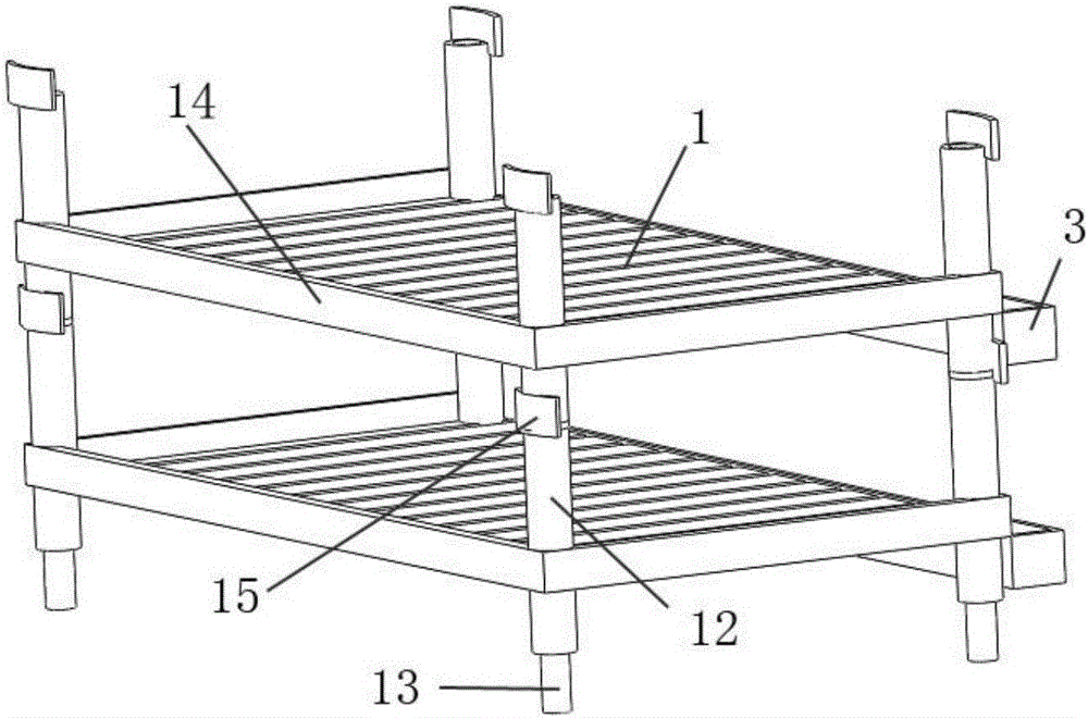
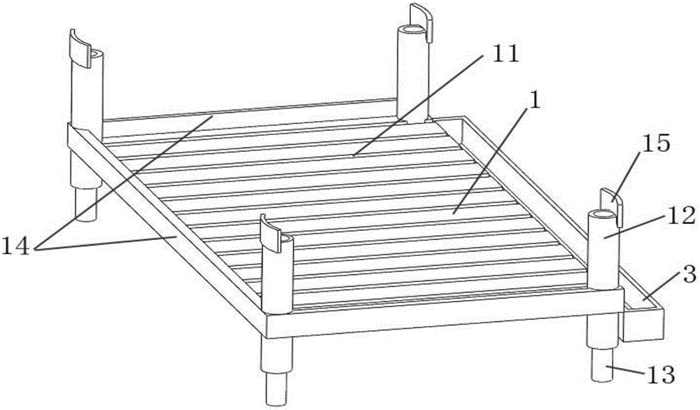
[0019] see figure 1 , a display rack for sheet metal parts processing, which consists of stacked two layers of racks; see figure 2 , image 3 , the shelf includes a laminate 1, a clamp 2 and a water tank 3;

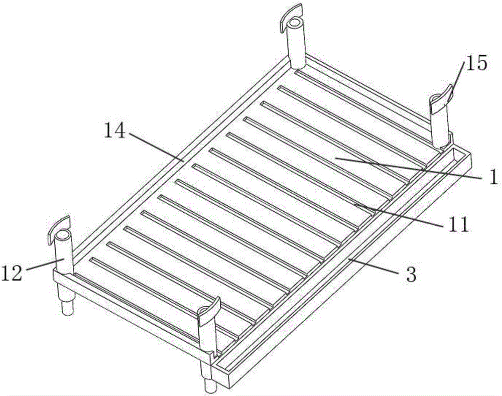
[0020] see Figure 4 , the laminate 1 is a flat plate, and the top surface of the laminate 1 is concavely distributed with a strip-shaped hydrophobic groove 11 along the width direction, and the hydrophobic groove 11 is a chute, that is, a chute with one end high and the other end low; The four corners of the surface are all vertically provided with connecting pipes 12, and the pipe holes of the connecting pipes 12 are tapered holes. An anti-skid layer is provided on the upper surface; the edge of the top surface of the laminate 1 is provided with a circle of coaming 14, and the coaming 14 at the lower end of the hydrophobic groove 11 is open; the four corners on the bottom of the laminate 1 Every place is vertically provided with connecting rod 13, and connecting ro...


PUM


Abstract

The invention relates to an arranging frame for sheet metal part machining. The arranging frame is formed by stacking two or more layers of shelves. Each shelf comprises a shelf plate, a clamping plate and a water collecting groove, wherein the shelf plate is a flat plate, strip-shaped water dredging grooves are distributed in the top face of the shelf plate in the width direction in a concave manner and are chutes, in other words, one end of each chute is high, and the other end of each chute is low. Connecting pipes are vertically arranged at the four corner positions of the top face of each shelf plate. Connecting rods are arranged at the four corner positions of the bottom face of each shelf plate. The clamping plates are transversely arranged on the shelf plate side faces on the outer sides of the lower ends of the water dredging grooves. The longitudinal sections of the clamping plates are in an L shape, the corners of the clamping plates are elastically bent, and longitudinal plates of the clamping plates are obliquely arranged inwards. The water collecting grooves are strip blocks with the middle portions downwards concaved to form grooves. One side face of each strip block is provided with a connecting plate. The connecting plates are clamped in the clamping plates, and the water collecting grooves and the clamping plates are detachably connected. The arranging frame is simple in structure and convenient and fast to operate, and dryness and tidiness of articles in all layers and stability of the arranging frame can be effectively guaranteed.

Description

technical field [0001] The invention belongs to the field of sheet metal parts, and in particular relates to a display rack for processing sheet metal parts. Background technique [0002] At present, there are many tooling used in the processing of sheet metal parts, which brings great convenience to people's processing. The existing auxiliary tooling racks mostly adopt the multi-layer board type, each layer board is provided with leak holes, and the boards are connected by straight rods, but there are the following defects: (1), because the multi-layer boards are equipped with Leakage holes make the water on the auxiliary tooling easily drip onto the articles on the lower floor, causing the articles on the lower floor to be unhygienic and unclean, and causing inconvenience for reuse; Make the countertop wet, time-consuming and laborious to clean each time, and reduce life efficiency; (3), when using the combined method of each layer and each layer, the corresponding straig...

Claims


Application Information

Patent Timeline
IPC IPC(8): B25H3/04
CPCB25H3/04
Inventor 徐振斌
Owner 马鞍山立信汽车零部件有限公司
Why Eureka
Try Eureka