
Heat preservation and sound insulation board demolding system

A sound insulation board and demoulding technology, applied in the direction of manufacturing tools, unloading devices, etc., can solve the problems of blocked mold passage in the production line, affecting production efficiency, etc., to reduce the movement stroke, reduce equipment energy consumption, and improve processing efficiency. Effect

Active Publication Date: 2021-12-03
山东威宝节能科技集团有限公司 +1
View PDF6 Cites 0 Cited by
  • Summary
  • Abstract
  • Description
  • Claims
  • Application Information

AI Technical Summary

Problems solved by technology

In order to improve the surface quality of the plate and facilitate the demoulding, the forming mold is generally equipped with a silicone lining. The demoulding device in the prior art includes a roller table, and a plate conveying mechanism is arranged above the roller table. When demoulding, the mold stays on the plate conveying In the upstream of the mechanism, the manipulator takes the plate out of the mold and places it on the plate conveying mechanism, and then the mold continues to be conveyed downstream. However, during the demoulding process, the silicone lining is easily adhered by the plate and warps upward. At this time, the silicone lining The height of the lining is higher than the height of the mold itself, so the mold will be stuck between the plate conveying mechanism and the roller table when passing under the plate conveying mechanism, which will block the passage of the mold in the entire production line and seriously affect the production efficiency

Method used


Image

  • Heat preservation and sound insulation board demolding system
  • Heat preservation and sound insulation board demolding system
  • Heat preservation and sound insulation board demolding system

Examples


Embodiment Construction

[0032] In order to make the objects and advantages of the present invention clearer, the present invention will be specifically described below in conjunction with examples. It should be understood that the following words are only used to describe one or several specific implementation modes of the present invention, and do not strictly limit the protection scope of the specific claims of the present invention.

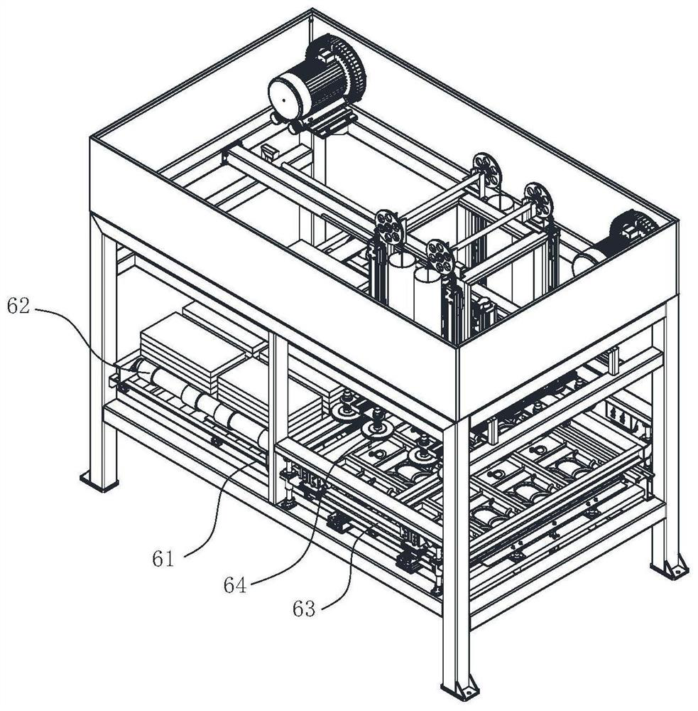
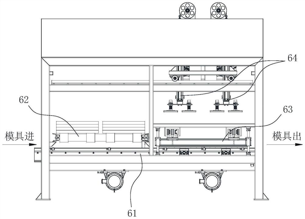
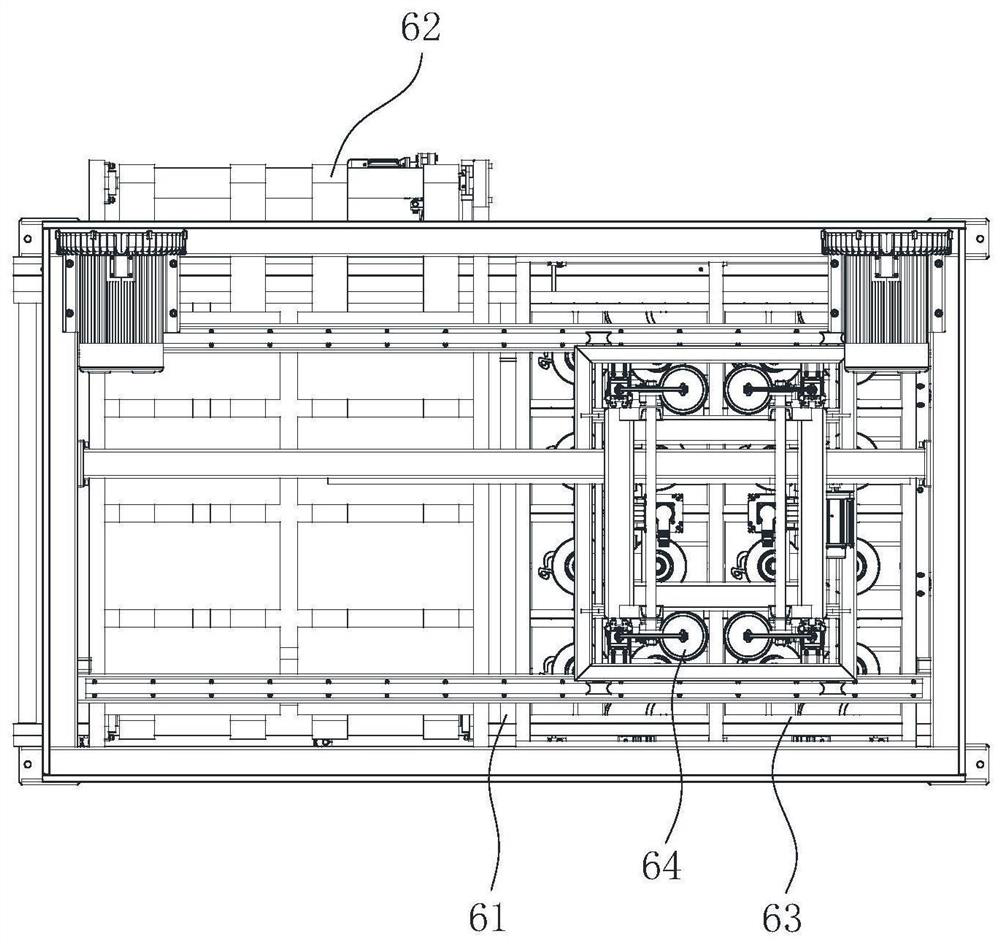
[0033] Such as Figures 1 to 5 As shown, a demoulding system for heat insulation and sound insulation panels includes: a first conveying device 61 for conveying a forming mold, the cavity of the forming mold is provided with an inner lining made of elastic material; and a second conveying device 62, used to transport the thermal insulation and sound insulation board after demolding; the compression molding device 63 is used to compress the forming mold on the first conveying device 61, and the compression molding device 63 has an edge with the thermal insulation and ...


PUM


Abstract

The invention belongs to the technical field of heat preservation and sound insulation board production and processing, and particularly relates to a heat preservation and sound insulation board demolding system. The heat preservation and sound insulation board demolding system comprises a first conveying device, a second conveying device, a mold pressing device and a mechanical arm. The conveying direction of the second conveying device is perpendicular to the conveying direction of the first conveying device. The second conveying device is located above the first conveying device and is spaced from the first conveying device by the distance of the thickness of at least one forming mold. In the conveying direction of the first conveying device, the second conveying device is located at the upstream of the mold pressing device. The second conveying device is arranged on the upstream portion of the mold pressing device, when a mold passes through the lower portion of the second conveying device, demolding is not conducted, so that the surface is flat, and the situation that the mold is clamped by the second conveying device is avoided; and after the mold is demolded at the mold pressing device, the mold is directly conveyed downstream, and even if the lining of the mold is upwarped, the lining of the mold cannot interfere with other equipment structures, and smooth operation of a production line is guaranteed.

Description

technical field [0001] The invention belongs to the technical field of production and processing of thermal insulation and sound insulation boards, and in particular relates to a demoulding system for thermal insulation and sound insulation boards. Background technique [0002] The heat insulation and sound insulation board is a kind of composite board with good heat insulation and sound insulation effect for buildings, which includes a prefabricated core board and a cement-based pouring layer. During processing, first inject the cement slurry into the mold, then put the core plate on the mold, compact the slurry, and combine with the core plate after the slurry solidifies, and finally remove the plate from the mold to obtain the product. In order to improve the surface quality of the plate and facilitate the demoulding, the forming mold is generally equipped with a silicone lining. The demoulding device in the prior art includes a roller table, and a plate conveying mechani...

Claims


Application Information

Patent Timeline
Patent Type & Authority Applications(China)
IPC IPC(8): B28B13/06B28B13/04
CPCB28B13/065B28B13/06B28B13/04
Inventor 邹明熊凤鸣
Owner 山东威宝节能科技集团有限公司
Learn More