Rail clamping device

A rail-clamping and rail-along technology, applied in the field of construction machinery, can solve the problems of large load, inability to achieve longitudinal positioning along the rail, and wear and tear, and achieve the effect of ensuring operational safety.

Active Publication Date: 2016-10-12
CRRC QINGDAO SIFANG CO LTD
View PDF7 Cites 0 Cited by
  • Summary
  • Abstract
  • Description
  • Claims
  • Application Information

AI Technical Summary

Problems solved by technology

[0002] At present, the equipment along the track is mostly used for cargo transportation, with a large load capacity, and the goods are stacked layer by layer, and the height is high. Usually, the equipment along the track mostly uses methods such as holding the rail waist and riding on the rail surface to run on the track. These operating modes Few constraints or no constraints at all make the equipment easy to roll when running along the rail, causing wear and tear, making it impossible to achieve longitudinal positioning along the rail

Method used


Image

  • Rail clamping device
  • Rail clamping device
  • Rail clamping device

Examples


Embodiment Construction

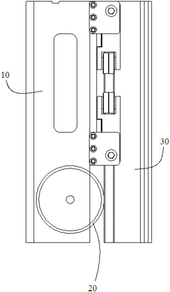
[0031] The core of the present invention is to provide a rail clamping device, the rail clamping device is installed on the wheel of the along-rail equipment, when the along-rail equipment is running, it can clamp the rail waist of the track, and adjust it in real time according to the operating conditions to realize the along-rail Longitudinal positioning improves operational safety.

[0032] In order to enable those skilled in the art to better understand the solution of the present invention, the present invention will be further described in detail below in conjunction with the accompanying drawings and specific embodiments.

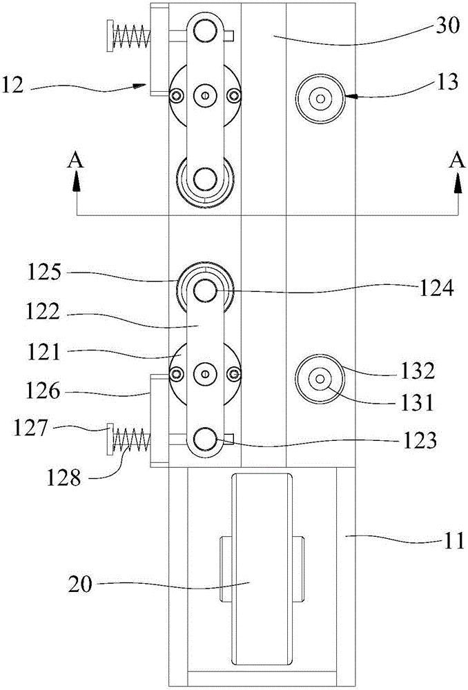
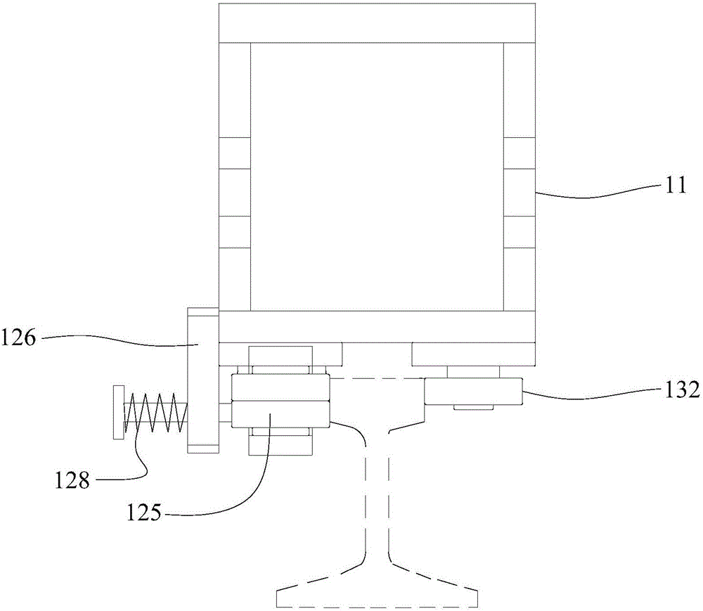
[0033] Please refer to Figure 1 to Figure 3 , figure 1 It is a structural schematic diagram of a wheel equipped with the rail clamping device provided by the present invention riding on the rail surface; figure 2 for figure 1 bottom view of image 3 for figure 2 A schematic diagram of the structure in the direction of A-A.

[0034] The rail ...


PUM


Abstract

The invention discloses a rail clamping device. The rail clamping device comprises a mounting base, wherein the mounting base is provided with an accommodating cavity for accommodating wheels of a device moving along a rail; adjusting components and positioning components, of which the positions are symmetrical, are mounted on the mounting base. The mounting base is configured in the following manner: the wheels ride on the surface of a rail, the adjusting components are arranged on one side of the rail, the positioning components are arranged on the other side of the rail, an adjusting bearing of each of the adjusting components and a positioning bearing of each of the positioning components are in contact with rail webs of the two sides of the rail, and the adjusting components can enable the adjusting bearings to be in contact with the rail webs of the rail. When the device moving along a rail, utilizing the rail clamping device disclosed by the invention, operates, the rail webs of the rail can be clamped, and besides, according to the operating situation, real-time adjustment is performed, so that longitudinal positioning along the rail is realized, and operation safety is improved.

Description

technical field [0001] The invention relates to the technical field of engineering machinery, in particular to a rail clamping device for equipment along the rail. Background technique [0002] At present, the track-along equipment is mostly used for cargo transportation, with a large load capacity, and the goods are stacked layer by layer, and the height is high. Usually, the track-along equipment mostly uses methods such as holding the rail waist and riding on the rail surface to run on the track. These operating modes Few constraints or no constraints at all make the equipment easy to roll when running along the rail, causing wear and tear, making it impossible to achieve longitudinal positioning along the rail. [0003] Therefore, how to design a rail clamping device that can realize the longitudinal positioning along the rail when the along-rail equipment is running is a technical problem to be solved by those skilled in the art. Contents of the invention [0004] Th...

Claims


Application Information

Patent Timeline
Patent Type & Authority Applications(China)
IPC IPC(8): B61H7/12
CPCB61H7/12
Inventor 吴向阳武秀媛张志毅陶传琦王银灵齐维闯国东芳迟建波万里
Owner CRRC QINGDAO SIFANG CO LTD
Why Eureka
Try Eureka