Limiting anti-bouncing device for upper acting coupler lifting rod

A coupler lifting rod and anti-jumping device technology, applied in traction devices, transportation and packaging, railway car body parts, etc., can solve problems such as abnormal unlocking of couplers, failure to install, derailment, etc., to ensure efficiency and order, installation and Easy to use, safe and reliable performance

Pending Publication Date: 2020-11-20
BAOJI CSR TIMES ENG MACHINERY
View PDF0 Cites 0 Cited by
  • Summary
  • Abstract
  • Description
  • Claims
  • Application Information

AI Technical Summary

Problems solved by technology

When the vehicle is running, it will be subjected to longitudinal impact and vertical vibration. When the impact and vibration reach a certain level, it will cause the coupler lever to swing greatly, resulting in abnormal unlocking of the coupler, causing accidents such as automatic separation of the train, rollover, derailment, etc. In severe cases, it will also affect the normal transportation efficiency and order of the railway, and cause immeasurable losses to human safety and the national economy.
Due to structural limitations, some existing rail vehicles cannot be installed with an anti-jump device for the coupler lift rod. There is a hidden danger of abnormal unlocking of the coupler due to malfunction of the coupler lift rod during vehicle operation. To solve this problem, it is necessary to carry out Improve

Method used


Image

  • Limiting anti-bouncing device for upper acting coupler lifting rod
  • Limiting anti-bouncing device for upper acting coupler lifting rod
  • Limiting anti-bouncing device for upper acting coupler lifting rod

Examples


Embodiment Construction

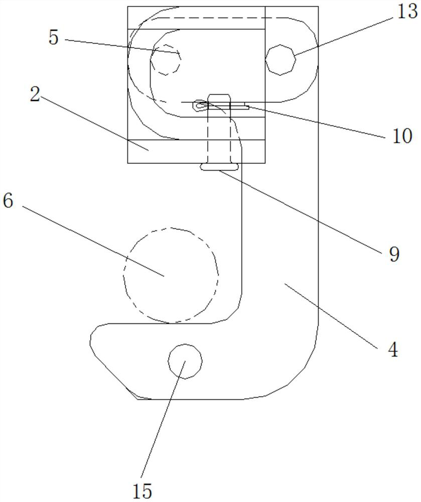
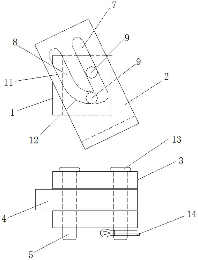
[0016] Attached below Figure 1-3 An embodiment of the present invention is described so as to clearly and completely describe the technical solution. Obviously, the described embodiment is only a part of the embodiments of the present invention, rather than all the embodiments.

[0017] In describing the present invention, it should be understood that the terms "upper", "lower", "front", "rear", "left", "right", "top", "bottom", "inner", " The orientation or positional relationship indicated by "outside", etc. is based on the orientation or positional relationship shown in the drawings, which is only for the convenience of describing the present invention and simplifying the description, rather than indicating or implying that the referred device or element must have a specific orientation, so as to Specific orientation configurations and operations, therefore, are not to be construed as limitations of the invention.

[0018] The limit and anti-jump device for the upper acti...


PUM


Abstract

The invention provides a limiting anti-bouncing device for an upper acting coupler lifting rod. A mounting plate and an lug plate seat positioned below the mounting plate are fixed on the end panel surface of a frame; one end of a hook plate is hooked on a coupler lifting rod, the other end of the hook plate is installed on the lug plate seat in a rotating mode, the hook plate is located on the lug plate seat through a locating pin shaft and a baffle located above the lug plate seat, the baffle is installed on the mounting plate in a vertical position and angle adjustable mode, and the vertical movement amount of the baffle is smaller than the length of the locating pin shaft. According to the invention, the phenomenon that the car coupler is abnormally unlocked due to large-amplitude swinging of the car coupler lifting rod under the impact and vibration of a car is avoided; and the railway normal transmission efficiency and order are ensured; the limiting anti-bouncing device is simple in structure, safe and reliable in performance, convenient to install and use, and capable of achieving the limiting anti-bouncing function of the upper acting coupler lifting rod on the premise that an original coupler lifting rod and an original installation base structure are not changed, the safety coefficient of the coupler in the using process is increased, and the running safety of a vehicle is guaranteed.

Description

technical field [0001] The invention belongs to the technical field of carriage connection of rail vehicles, and in particular relates to a position-limiting and anti-jumping device for an upper-acting coupler handle. Background technique [0002] As one of the most basic and important parts of the vehicle, the coupler buffer device is located between the locomotive and the vehicle or between the vehicle and the vehicle. It plays a decisive role in improving the safety, stability and comfort of vehicle operation. When the vehicle is running, it will be subjected to longitudinal impact and vertical vibration. When the impact and vibration reach a certain level, it will cause the coupler lever to swing greatly, resulting in abnormal unlocking of the coupler, causing accidents such as automatic separation of the train, rollover, derailment, etc. When it is serious, it will also affect the normal transportation efficiency and order of the railway, and cause immeasurable losses ...

Claims


Application Information

Patent Timeline
Patent Type & Authority Applications(China)
IPC IPC(8): B61G9/04B61G9/20
CPCB61G9/04B61G9/20
Inventor 杨汉文王敏邢佳王琛朱世昌苗武王旭超李田朱红军吴庆立陈毅马爱军罗文彬朱红飞
Owner BAOJI CSR TIMES ENG MACHINERY
Why Eureka
Try Eureka