Electric cash door

A banknote door and electric technology, applied in the direction of handling coins or valuable banknotes, coin accepting devices, instruments, etc., can solve the problems of mutual replacement, difficult installation, narrow application range, etc., to improve applicability and replaceability , The operation process is convenient and the effect of a wide range of applications

Active Publication Date: 2015-11-18
GUANGZHOU KINGTELLER ATM TECH
View PDF5 Cites 3 Cited by
  • Summary
  • Abstract
  • Description
  • Claims
  • Application Information

AI Technical Summary

Problems solved by technology

The structure of the existing banknote door mechanism is relatively complicated, the installation is difficult, and the production cost is high
In addition, the existing banknote door mechanism has an opaque steel plate and a transparent plastic plate. The structures required for these two door panels are completely different, and they cannot be replaced with each other on the same type of financial equipment, making their integration low. , with a narrow scope of application

Method used


Image

  • Electric cash door
  • Electric cash door
  • Electric cash door

Examples


Embodiment 1

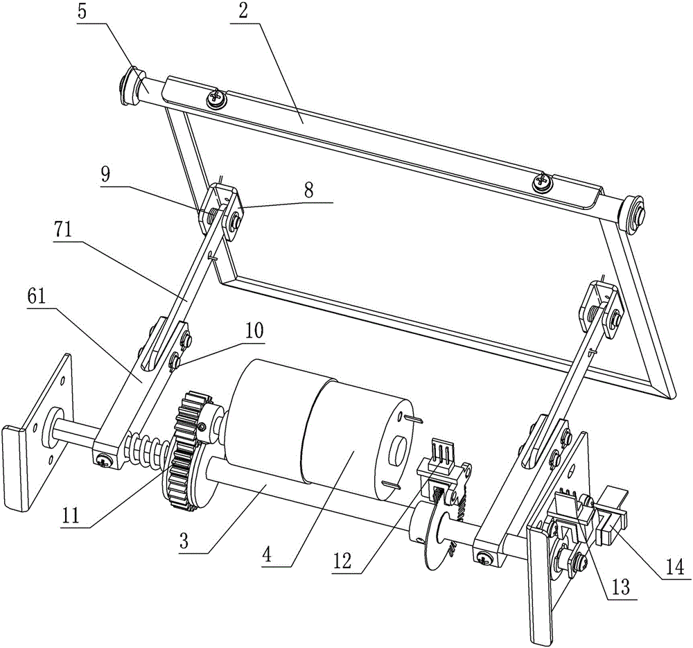
[0010] Embodiment one, such as Figure 1-4 shown.

[0011] An electric bank note door, comprising a fixed frame 1 and a door panel 2 for banknote output after opening, the frame is equipped with a drive shaft 3 that rotates around its own axis, and a drive motor 4 that drives the drive shaft to move, and can rotate around its own axis The rotating shaft 5, the two fixed ends of the rotating shaft are installed on the frame, and the door panel is fixedly connected with the shaft body of the rotating shaft; there is a link mechanism that transmits the driving force to the door panel, and the link mechanism includes a link mechanism fixedly installed on the drive shaft drive rod, and the driven rod that pushes the door panel to rotate around the rotating shaft, one end of the driven rod is hinged with the driving rod, and the other end is hinged with the positioning block 8 fixed on the door panel or the rotating shaft; The resetting mechanism 9 that moving rod resets.

[0012]...

Embodiment 2

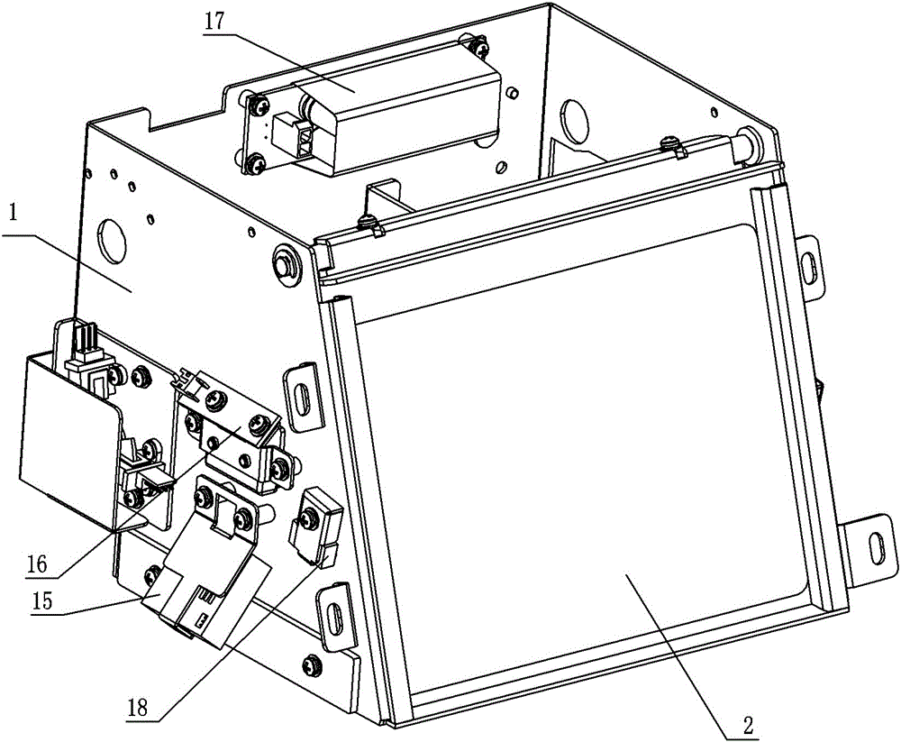
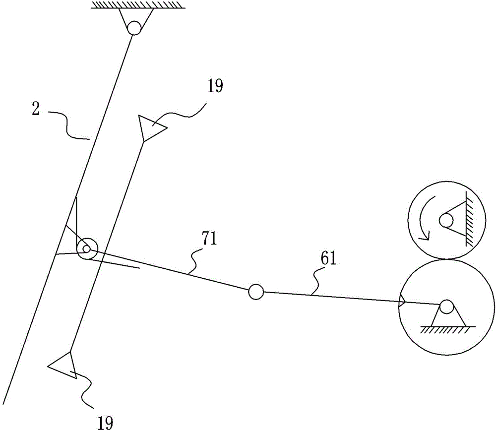
[0014] Embodiment two, such as Figure 5-8 shown.

[0015] The door panel 2 is a transparent plastic door panel, and the driving rod includes a swing block 62, and a driving lever 63 that is rotated by the swing block. The swing block is connected to the driving motor 4 and is driven by the driving motor. The driving rod is V-shaped, and the middle part is fixed. On the driving shaft, one end can be pressed against the swing block, and the other end is hinged with the driven rod; the positioning block 8 is fixedly installed on the rotating shaft 5 and rotates with it, and the driven rod is connected to the driving rod and the positioning block at both ends Hinged swing lever 72; reset mechanism 9 is a torsion spring, the torsion spring is sleeved on the rotating shaft 5 and drives it to drive the door panel 2 to close; the rest is the same as the first embodiment.

[0016] The driving motor drives the oscillating block to swing, and the oscillating block presses against a V-s...


PUM


Abstract

An electric cash door is disclosed. A door plate, that could be a transparent steel door plate or transparent plastic door plate, is arranged on the door frame. During working, a driving motor drives a driving shaft and a linkage mechanism to open the door plate and a resetting-mechanism to close the door plate. The electric cash door is opened by the linkage mechanism to drive the door plate. The electric cash door is simple in structure and convenient for operation and is stable and rapid. The structure is also applicable to steel plate door plate and transparent plastic door plate. The electric cash door is high in integration level, and wide in application scope, and the applicability and replacing convenience of a financial device are greatly improved.

Description

technical field [0001] The invention relates to financial equipment, in particular to an electric banknote door for electronically controlling banknote output. Background technique [0002] The cash-out door is usually arranged on the financial equipment. The structure of the existing banknote door mechanisms is relatively complicated, difficult to install, and high in production cost. In addition, the existing banknote door mechanism has an opaque steel plate and a transparent plastic plate. The structures required for these two door panels are completely different, and they cannot be replaced with each other on the same type of financial equipment, making their integration low. , the scope of application is narrow. Contents of the invention [0003] The present invention aims to provide an electric banknote door with simple structure and convenient operation, and further makes it suitable for different types of door panel structures, improving its application range and...

Claims


Application Information

Patent Timeline
Patent Type & Authority Applications(China)
IPC IPC(8): G07D11/00
Inventor 徐德银蒲文涛刘鹏杨程黎国俊蔡晓兵
Owner GUANGZHOU KINGTELLER ATM TECH
Why Eureka
Try Eureka