Novel no-driver touch screen real-time diagnostic system
A real-time diagnosis and touch screen technology, applied in signal transmission system, non-electrical signal transmission system, instrument, etc., can solve problems such as data collection and fault diagnosis of inoperable faults and errors
- Summary
- Abstract
- Description
- Claims
- Application Information
AI Technical Summary
Problems solved by technology
Method used
Image

Examples
Embodiment 1
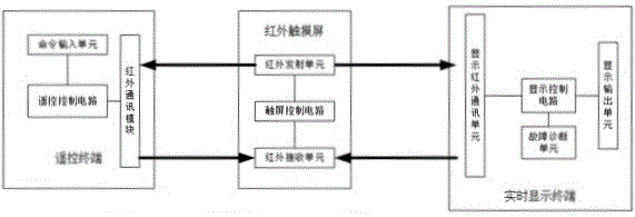
[0025] like figure 2 As shown, the infrared touch screen includes an infrared emitting unit, an infrared receiving unit and a touch screen control circuit, and the infrared receiving unit and the infrared emitting unit are respectively electrically connected to the touch screen control circuit. The infrared emitting unit and the infrared receiving unit are respectively composed of an infrared emitting tube and an infrared receiving tube arranged around the outer frame of the infrared touch screen to form an infrared detection network on the surface of the screen. When working, the infrared emitting unit and the infrared receiving unit scan the screen on the coordinated control line of the touch screen control circuit. When the infrared touch screen is operated, the infrared light emitted by the infrared emitting tube corresponding to the contact position is blocked, so that the infrared light received by the infrared receiving tube corresponding to the contact position change...
Embodiment 2
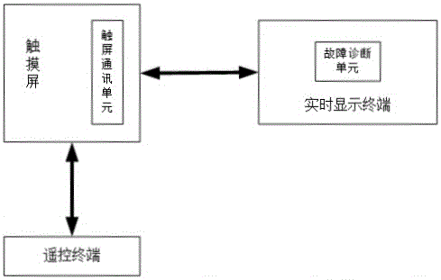
[0032] The driverless touch screen real-time diagnosis system described in the second embodiment has many similarities with the first embodiment. For the sake of brevity, this embodiment focuses on the differences. For the similarities, please refer to the description of the first embodiment. like Figure 4 As shown, the infrared touch screen in Embodiment 1 further includes a touch screen communication unit, and the touch screen communication unit is electrically connected to the touch screen control circuit. It is used for data communication between infrared touch screen and remote control terminal. In this embodiment, the remote control communication unit and the touch screen communication unit have the same wireless communication mode to complete the data communication between the remote control terminal and the infrared touch screen. Therefore, the remote control communication unit and the touch screen communication unit may be one or more of an infrared communication mo...
Embodiment 3
[0036] The driveless touch screen real-time diagnosis system described in the third embodiment has many similarities with the first embodiment. For the sake of brevity, this embodiment focuses on the differences. For the similarities, please refer to the description of the first embodiment. like Figure 5 As shown, the infrared touch screen in Embodiment 1 further includes an infrared receiving device, and the infrared receiving device is electrically connected to the touch screen control circuit. Embodiment 1 The remote control communication unit uses an infrared communication module. The infrared touch screen uses an infrared receiving device to receive the data transmitted by the infrared communication module of the remote control terminal, and at the same time still uses the infrared emission unit of the touch screen to transmit data to the infrared communication module of the remote control terminal. In this embodiment, while the detection accuracy of the infrared touch ...
PUM
 Abstract
Description
Claims
Application Information
 - R&D
- Intellectual Property
- Life Sciences
- Materials
- Tech Scout
- Unparalleled Data Quality
- Higher Quality Content
- 60% Fewer Hallucinations
Browse by: Latest US Patents, China's latest patents, Technical Efficacy Thesaurus, Application Domain, Technology Topic, Popular Technical Reports.
© 2025 PatSnap. All rights reserved.Legal|Privacy policy|Modern Slavery Act Transparency Statement|Sitemap|About US| Contact US: help@patsnap.com