
Pneumatic tire and its manufacturing method

A technology for pneumatic tires and manufacturing methods, which is applied to pneumatic tires, tire parts, tire treads/tread patterns, etc., can solve the problems of easy perforation and easy trauma, reduce cavity resonance, and improve repair efficiency. Effect

Active Publication Date: 2017-04-26
BRIDGESTONE CORP
View PDF6 Cites 0 Cited by
  • Summary
  • Abstract
  • Description
  • Claims
  • Application Information

AI Technical Summary

Problems solved by technology

This tire has the problem that the side with a higher negative ratio of the tread pattern (the ratio of the groove portion (non-contact portion) in the tread) is subject to a higher contact pressure, and thus is susceptible to external damage during running and is more prone to perforated

Method used


Image

  • Pneumatic tire and its manufacturing method
  • Pneumatic tire and its manufacturing method
  • Pneumatic tire and its manufacturing method

Examples


Embodiment 1 and comparative example 1 and comparative example 2

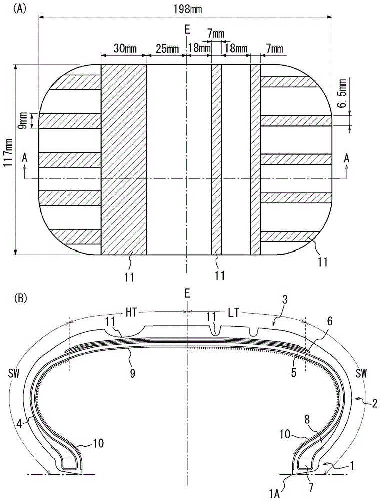
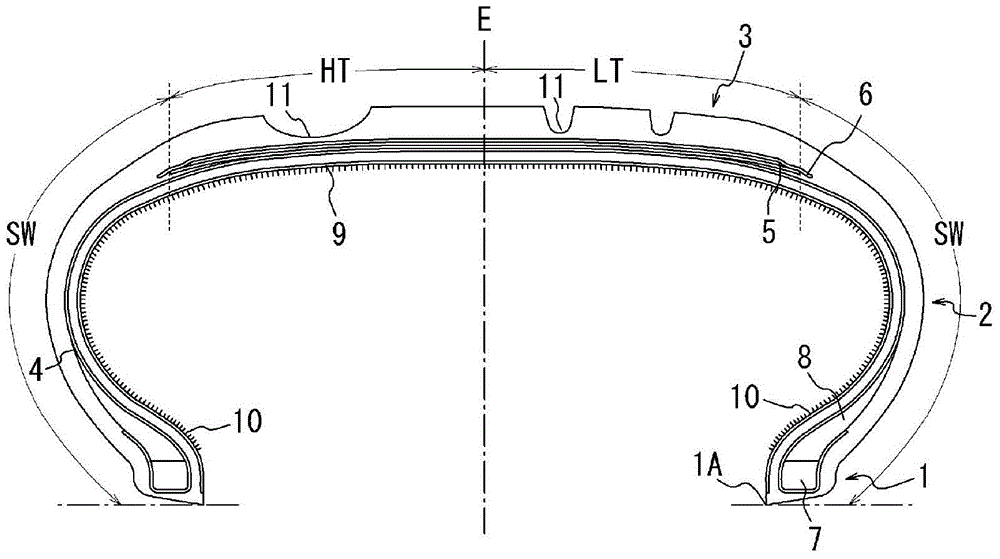
[0054] prepared with such figure 1 A tire of the same specification with the tread pattern shown, with or without short fibers made of nylon attached to predetermined areas by flocking. The cavity resonance and puncture repair efficiency of each tire were measured as described below. The tires used are those with figure 1 Tire size 255 / 35R20 for the construction shown. Specifically, the tread portion of each tire is divided into two sides by the equatorial plane E, that is, the serial side (tread half HT) and the reverse serial side (tread half LT), and the serial side Set the negative ratio to 48%, and set the negative ratio on the reversed side to 26%. Use 8.5J-20 rims. Note that the maximum width BW in the tire width direction of each belt layer is 78% of the maximum width of the tire.

[0055] Example 1 is as figure 1 The region (excluding the rim mounting portion) of the tire inner peripheral surface from the equatorial plane E to the tire radially inner end portion...


PUM

PropertyMeasurementUnit
lengthaaaaaaaaaa
lengthaaaaaaaaaa
diameteraaaaaaaaaa

Abstract

To provide a pneumatic tire provided with a tread having a pattern that is asymmetric with respect to the tire equatorial plane as a boundary, wherein the tire can be easily manufactured and cavity resonance can be reliably reduced without reducing repair efficiency . A method of manufacturing the pneumatic tire is also provided. The pneumatic tire is provided with an asymmetrical tread pattern in which a negative ratio of a pair of tread halves between the tire equatorial plane on the tread portion and both outer ends in the tire width direction of the tread portion for the two tread halves On the other hand, this pneumatic tire is characterized in that short fibers are fixed to at least a part of the tire inner peripheral surface of the tread portion, and the short fiber fixed area ratio of the tread half having a higher negative ratio is shorter than that of the other tread half. Fiber fixed area rate is low.

Description

technical field [0001] The present invention relates to a pneumatic tire and its manufacturing method. Background technique [0002] It is known that a pneumatic tire exhibits a cavity resonance phenomenon caused by the length of a round tube inside the tire due to its structure. In addition, regardless of the type of the pneumatic tire, the pneumatic tire generates noise in the range of 200 Hz to 270 Hz according to the cavity resonance frequency thereof, which is a main cause of unpleasant interior noise. [0003] As described above, since the air resonance inside the tire is the cause of the noise inside the vehicle, the method for absorbing the noise inside the tire is effective as an improved method. Examples of proposed conventional methods include a technique disclosed in Patent Document 1 of bonding short fibers to the inner peripheral surface of a tire. [0004] In addition, from the viewpoint of wear resistance and the like, some passenger car tires employ a trea...

Claims


Application Information

Patent Timeline
Patent Type & Authority Patents(China)
IPC IPC(8): B60C5/00B29D30/06B60C11/03B60C11/04
CPCB60C11/0332B60C11/0306B60C19/002B60C11/0304B60C11/033B29D30/06B60C11/03B60C5/00B05D1/14
Inventor 渡边敏幸
Owner BRIDGESTONE CORP
Learn More