Pneumatic tire and manufacturing method thereof

A technology for pneumatic tires and tire width directions, applied to pneumatic tires, tire parts, tires, etc., can solve problems such as deterioration of fuel consumption and increase of rolling resistance of tire weight, and achieve the purpose of suppressing the deterioration of riding comfort and suppressing rolling resistance The effect of increasing and suppressing cavity resonance

Inactive Publication Date: 2014-06-04
BRIDGESTONE CORP
View PDF6 Cites 1 Cited by
  • Summary
  • Abstract
  • Description
  • Claims
  • Application Information

AI Technical Summary

Problems solved by technology

[0008] However, attaching the short fibers to the entire area of ​​the inner peripheral surface of the tire as described in Patent Document 1 raises the problem that the weight of the tire and the rolling resistance increase, which deteriorates the fuel consumption of a vehicle mounted with such a tire

Method used


Image

  • Pneumatic tire and manufacturing method thereof
  • Pneumatic tire and manufacturing method thereof
  • Pneumatic tire and manufacturing method thereof

Examples


Embodiment 1 and comparative example 1 and comparative example 2

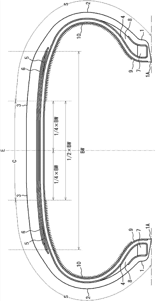
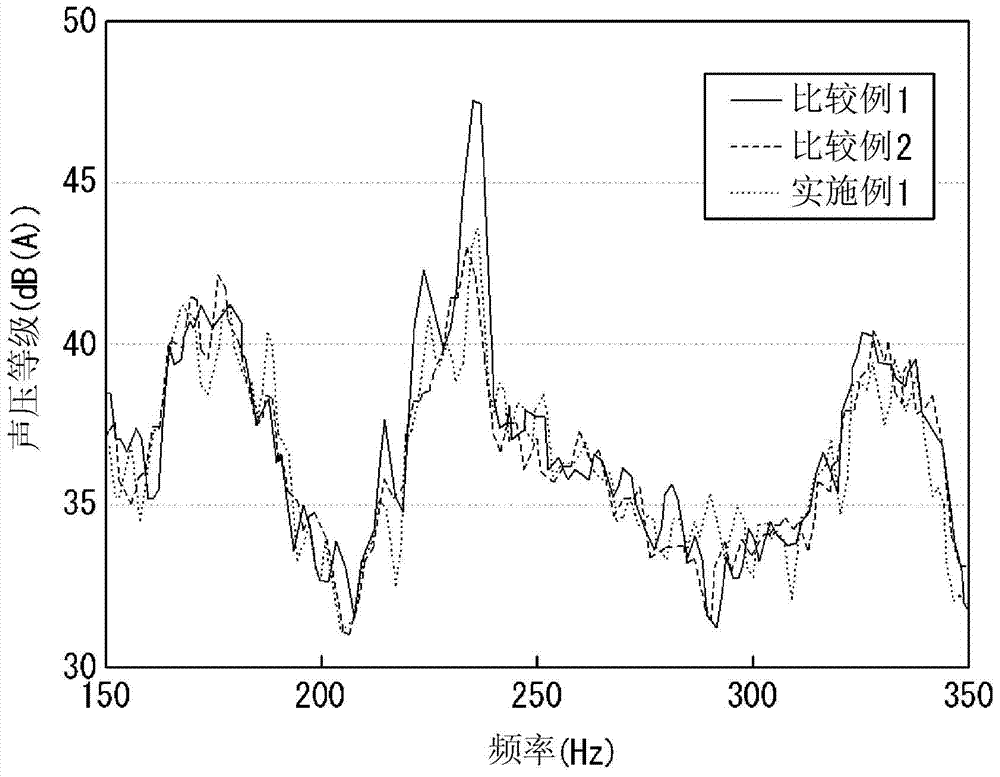
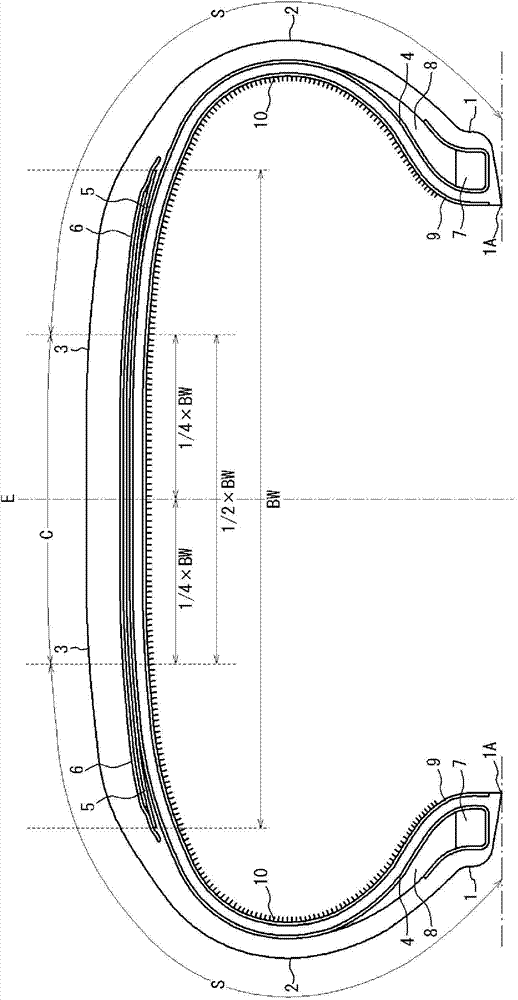
[0062] Test tires (Example 1) in which short fibers were provided in each tire side region of the tire inner peripheral surface by electrostatic flocking processing were respectively prepared by using tires sharing the same specifications in other details, in the tire inner peripheral surface A test tire without short fibers (Comparative Example 1) and a test tire with short fibers provided on the entire inner peripheral surface of the tire by electrostatic flocking (Comparative Example 2). The interior noise of an actual vehicle was measured for each of the test tires by the method described below.

[0063] In the test tire of Example 1, about 20 g of short fibers made of nylon (fiber thickness: 15 denier (denier) = φ45 μm, fiber length: 2.5 mm) were attached to each tire side region by electrostatic flocking inner surface of the tire (approximately 20,000 short fibers / square centimeter). In the tire of Example 1, the ratio of the area of ​​the tire inner peripheral surface ...

Embodiment 2 to Embodiment 4

[0069] Except for the ratio of the area of ​​the sub-region to which short fibers are fixedly attached to the tire inner peripheral surface of each tire side region of Examples 2 to 4 and the overall area of ​​the tire inner peripheral surface of each tire side region as shown in Table 1 Test tires of Examples 2 to 4 were prepared in the same manner as in Example 1 except for the changes shown. For each test tire, the interior noise was measured by the method described above. The sound pressure reduction amounts of the test tires at the peak around 235 Hz (at which the noise reduction effect is observed to be most significant) are shown in Table 1 using index values ​​relative to the results of Comparative Example 1 as a reference.

[0070] [Table 1]

[0071]

[0072] As can be understood from the results shown in Table 1, in terms of satisfactorily reducing the cavity resonance sound of the tire, it is preferable in the inner peripheral surface of the tire that the sub-re...

Embodiment 5 to Embodiment 8

[0074] Test tires of Examples 5 to 8 were prepared in the same manner as in Example 1 except that the number of short fibers per square centimeter was changed in Examples 5 to 8 as shown in Table 2. The interior noise of each test tire was measured by the method described above. The sound pressure reduction amounts of the test tires at the peak near 235 Hz (at which the noise reduction effect is observed to be most significant) are shown in Table 2 using index values ​​relative to the results of Comparative Example 1 as a reference.

[0075] [Table 2]

[0076]

[0077] As can be understood from the results shown in Table 2, in terms of satisfactorily reducing the cavity resonance sound of the tire, it is preferable that the number of short fibers per square centimeter is 100 fibers / square centimeter or more, more preferably 1000 fibers / cm2 or more.


PUM

PropertyMeasurementUnit
lengthaaaaaaaaaa
diameteraaaaaaaaaa
lengthaaaaaaaaaa

Abstract

The present invention relates to a pneumatic tire that is easy to manufacture and that can reliably reduce cavernous resonance, and more particularly relates to a pneumatic tire having short fibers (10) fixed to at least a portion of the internal peripheral surface, and having a belt (5) embedded in a tread portion (3), the belt being composed of one or more belt layers and having a width (BW) in the tire width direction of the belt layer furthest to the inside in the tire radial direction, the pneumatic tire being characterized in that, in the tire width cross-section, a tire center region (C) that is composed of a range of 1 / 2 BW in the tire width direction centered on the tire equatorial plane (E), and tire side region (S) that is composed of a region from the outer edge portion of the tire center region (C) in the tire width direction to the inner edge portion of a bead portion (1); in the tire radial direction, satisfy the relationship of the following formula (1) with respect to the tire internal peripheral surface. Formula (1): fixing surface area of short fibers in the tire center region / surface area of the tire center region < fixing surface area of short fibers in the tire side region / surface area of the tire side region.

Description

technical field [0001] The present invention relates to a pneumatic tire and a method for manufacturing the pneumatic tire. In particular, the present invention relates to a low road noise tire in which a plurality of short fibers are vertically provided on the inner peripheral surface of each side region of the tire in order to reduce cavity resonance sound, and a method of manufacturing the low road noise tire. Background technique [0002] It is known that a pneumatic tire exhibits a cavity resonance phenomenon controlled by the length of a circular tube inside the tire due to the structure of the pneumatic tire. Regardless of the type of the pneumatic tire, the pneumatic tire generates tire road noise with a cavity resonance frequency in the range of 200 Hz to 270 Hz depending on the circumference of the pneumatic tire, and the tire road noise is a main cause of unpleasant interior noise. [0003] Since air resonance inside tires is a major cause of interior noise as de...

Claims


Application Information

Patent Timeline
Patent Type & Authority Applications(China)
IPC IPC(8): B60C5/00B29D30/30
CPCB60C19/002B29D30/0061B29D30/0681
Inventor 渡边敏幸和气充幸石原大雅
Owner BRIDGESTONE CORP
Why Eureka
Try Eureka