Combined crusher
A crusher and combined technology, which is applied in the direction of grain processing, etc., can solve the problems that the coarse-grained materials at the end of the sieve plate cannot be discharged in time, the feeding particle size cannot be too large, and the materials are easy to block, so as to achieve large crushing ratio and product particle size. Small, non-clogging effect
- Summary
- Abstract
- Description
- Claims
- Application Information
AI Technical Summary
Problems solved by technology
Method used
Image
Examples
Embodiment 1
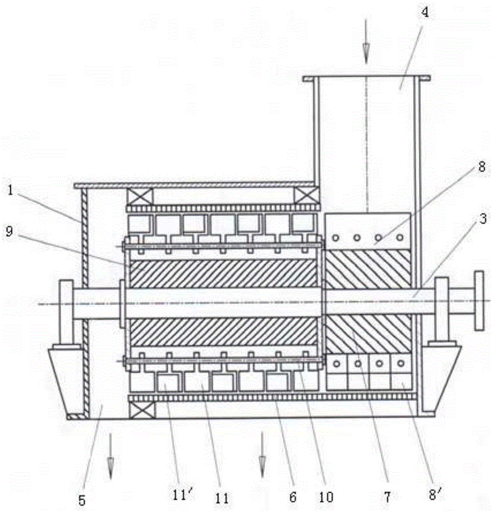
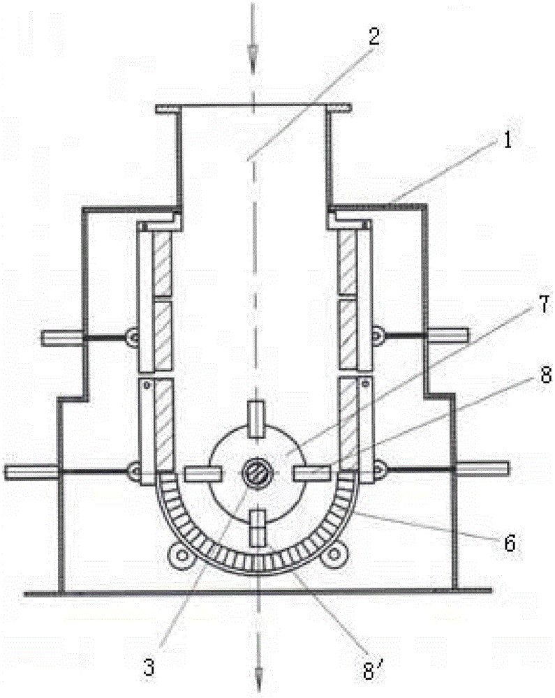
[0038] See attached figure 1 And attached figure 2 , with figure 1 And attached figure 2 A specific embodiment of a combined crusher is provided, wherein, the attached figure 1 It is the front view of the combined crusher, attached figure 2 It is the right view of the combined crusher.
[0039] as attached figure 1 And attached figure 2 As shown, the combined crusher includes a casing 1. A crushing chamber 2 is provided in the casing 1. The crushing chamber 2 is used to provide a crushing place for materials. A rotating shaft 3 is provided in the crushing chamber 2.
[0040] A material inlet 4 is arranged at the front end of the rotating shaft 3, and the material inlet 4 is used for inputting materials to be crushed.
[0041] In this embodiment, in order to facilitate the input of materials, the material inlet 4 is arranged on the top of the casing 1, so that the material to be crushed can be poured directly from the top inlet 4, which is beneficial to the input of ...
Embodiment 2
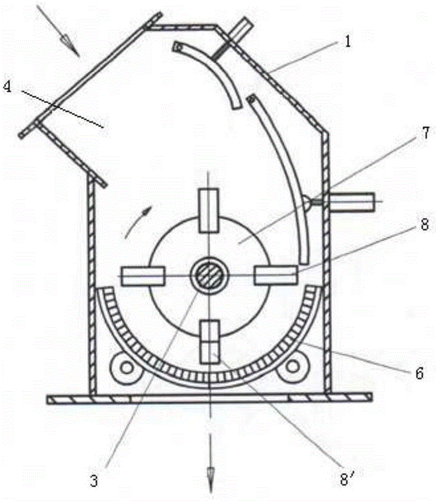
[0061] See attached image 3 , with image 3 Another specific embodiment of the combined crusher is provided, wherein, the attached image 3 It is the right view of the combined crusher.
[0062] as attached image 3 shown, with image 3 In the embodiment provided in the material inlet 4 is biased to one side, so that a certain slope will be formed at the material inlet 4, which is more conducive to the input of materials.
[0063] Compared with the structure provided by Embodiment 1, the structure provided by this embodiment can generally only rotate in one direction, while the rotor 7 provided by Embodiment 1 can rotate bidirectionally.
Embodiment 3
[0065] See attached Figure 4 And attached Figure 5 , with Figure 4 And attached Figure 5 A conversion embodiment of the combined crusher of the present invention is provided, wherein, the attached Figure 4 And attached Figure 5 Both are the right view of the combined crusher.
[0066] as attached Figure 4 And attached Figure 5 As shown, for the solution provided by the present invention, the following equivalent conversion can also be carried out, for example, the material-moving blow bar 8' installed on the previous rotor 7 is replaced by the material-moving hammer head 11', so that it can also be used to a certain extent realize the effect of the present invention.
[0067] Of course, the installation method of the material transfer hammer head 11' in this embodiment can be directly installed on the rotor 7, or the method provided in this embodiment can be used to add a hammer shaft 10, and then set the material transfer hammer on the hammer shaft 10. Hammerh...
PUM
 Abstract
Description
Claims
Application Information
 - R&D
- Intellectual Property
- Life Sciences
- Materials
- Tech Scout
- Unparalleled Data Quality
- Higher Quality Content
- 60% Fewer Hallucinations
Browse by: Latest US Patents, China's latest patents, Technical Efficacy Thesaurus, Application Domain, Technology Topic, Popular Technical Reports.
© 2025 PatSnap. All rights reserved.Legal|Privacy policy|Modern Slavery Act Transparency Statement|Sitemap|About US| Contact US: help@patsnap.com


