Screw rod electric clamp

An electric and screw technology, applied in the direction of workpiece clamping devices, manufacturing tools, etc., can solve the problems of simple structure, complex structure, high labor cost, etc., and achieve the effect of strong clamping, tight fit and flexible control

Inactive Publication Date: 2015-11-25
STATE GRID FUJIAN ELECTRIC POWER CO LTD +2
View PDF5 Cites 45 Cited by
  • Summary
  • Abstract
  • Description
  • Claims
  • Application Information

AI Technical Summary

Problems solved by technology

The manual clamping device is inconvenient to operate, and the labor cost is high, so the electric clamping device is the mainstream of application
However, some of the clamping devices that appear on the market are simple in structure but not effective in use, and some other effects are good but the structure is too complicated

Method used


Image

  • Screw rod electric clamp
  • Screw rod electric clamp

Examples


Embodiment Construction

[0020] The present invention will be further described below in conjunction with the accompanying drawings and embodiments.

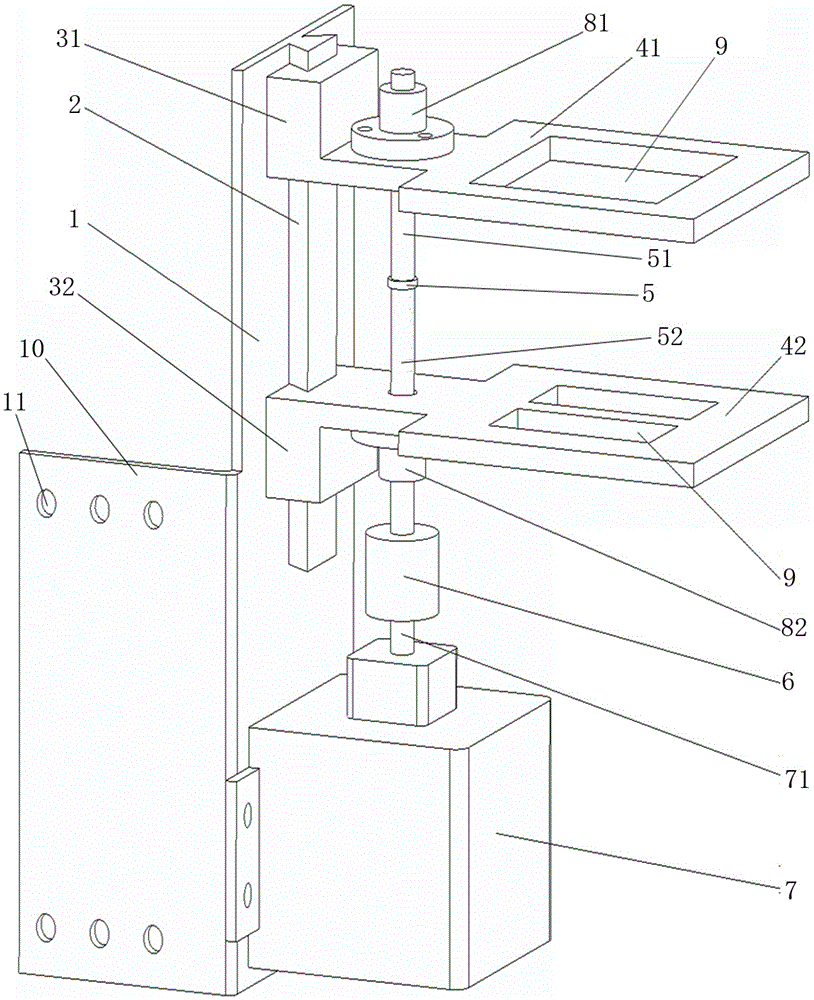
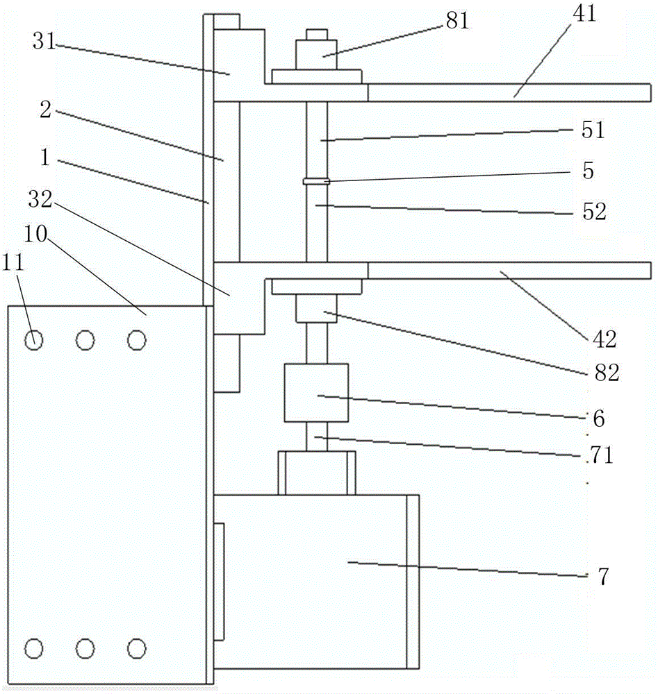
[0021] Please refer to figure 1 and figure 2 , this embodiment provides a screw electric clamp, which is characterized in that it includes a fixed plate 1, a slide rail 2 is arranged on one side of the fixed plate 1, and a corresponding Coordinated upper slider 31 and lower slider 32, the slide rail 2 and the chute of the upper and lower sliders are all dovetail-shaped structures, ensuring that the slide rail 2 is closely matched with the upper slider 31 and lower slider 32, and is not easy to fall off , the upper slider 31 is connected with an upper splint 41, preferably, the upper slider 31 is integrally formed with the upper splint 41, and the lower slider 32 is connected with the lower splint 42, preferably, the The lower slider 32 is integrally formed with the lower splint 42, the upper splint 41 and the lower splint 42 are connected through a t...


PUM


Abstract

The invention relates to a screw rod electric clamp. The screw rod electric clamp comprises a fixed plate. A sliding rail is arranged on one side of the fixed plate. An upper sliding block and a lower sliding block which are matched with the sliding rail are arranged on the sliding rail from top to bottom. The upper sliding block is connected with an upper clamping plate. The lower sliding block is connected with a lower clamping plate. The upper clamping plate and the lower clamping plate are connected through a bidirectional screw rod. The direction of a thread on the upper section of the bidirectional screw rod is opposite to the direction of a thread on the lower section of the bidirectional screw rod. The upper section of the bidirectional screw rod is connected with the upper clamping plate. The lower section of the bidirectional screw rod is connected with the lower clamping plate. The lower end of the bidirectional screw rod penetrates through the lower clamping plate, and then is connected with a motor through a coupler. The motor drives the bidirectional screw rod to rotate to achieve the nearness or separation of the upper clamping plate and the lower clamping plate. According to the screw rod electric clamp, the motor drives the screw rod to rotate, so that the working state of the clamping device is controlled; the control is flexible and convenient; the clamping effect is good.

Description

technical field [0001] The invention relates to a screw rod electric clamp. Background technique [0002] In production and life, clamping devices are required in many occasions, such as field testing of transformers, packaging products in industrial production, and many other occasions. The manual clamping device is inconvenient to operate, and the labor cost is high, so the electric clamping device is the mainstream of application. However, some clamping devices that appear on the market are simple in structure but not effective in use, and some other effects are good but the structure is too complicated. Contents of the invention [0003] The object of the present invention is to provide a screw rod electric clamp, which controls the working state of the clamping device through the rotation of the screw rod driven by the motor, which is flexible and convenient to control and has good clamping effect. [0004] In order to achieve the above object, the present invention...

Claims


Application Information

Patent Timeline
Patent Type & Authority Applications(China)
IPC IPC(8): B25B11/00
CPCB25B11/00
Inventor 高琛钟小强郭志伟鄢盛腾张屹鲁君成
Owner STATE GRID FUJIAN ELECTRIC POWER CO LTD
Why Eureka
Try Eureka