Resonant compensation topology variable magnetic coupling resonant wireless electric energy transmission device and method

A technology of wireless power transmission and magnetic coupling resonance, which is applied in the direction of circuit devices, battery circuit devices, transportation and packaging, etc., can solve the problems that the wireless power transmission system cannot meet the requirements efficiently, and reduce the difficulty of control and reduce the number of switches. Loss, flexible control effects

Inactive Publication Date: 2017-06-13
SHANDONG UNIV
View PDF4 Cites 53 Cited by
  • Summary
  • Abstract
  • Description
  • Claims
  • Application Information

AI Technical Summary

Problems solved by technology

However, due to the mechanism and characteristics of the battery, the internal resistance of the battery is constantly changing during the charging process. Even the simplest and most commonly used charging method - constant current and constant voltage charging strategy has two working stages: constant current stage and constant voltage stage , the wireless power transfer system using a single resonance compensation scheme cannot efficiently meet its requirements

Method used


Image

  • Resonant compensation topology variable magnetic coupling resonant wireless electric energy transmission device and method
  • Resonant compensation topology variable magnetic coupling resonant wireless electric energy transmission device and method
  • Resonant compensation topology variable magnetic coupling resonant wireless electric energy transmission device and method

Examples


Embodiment Construction

[0037] The present invention will be further described below in conjunction with the accompanying drawings and embodiments.

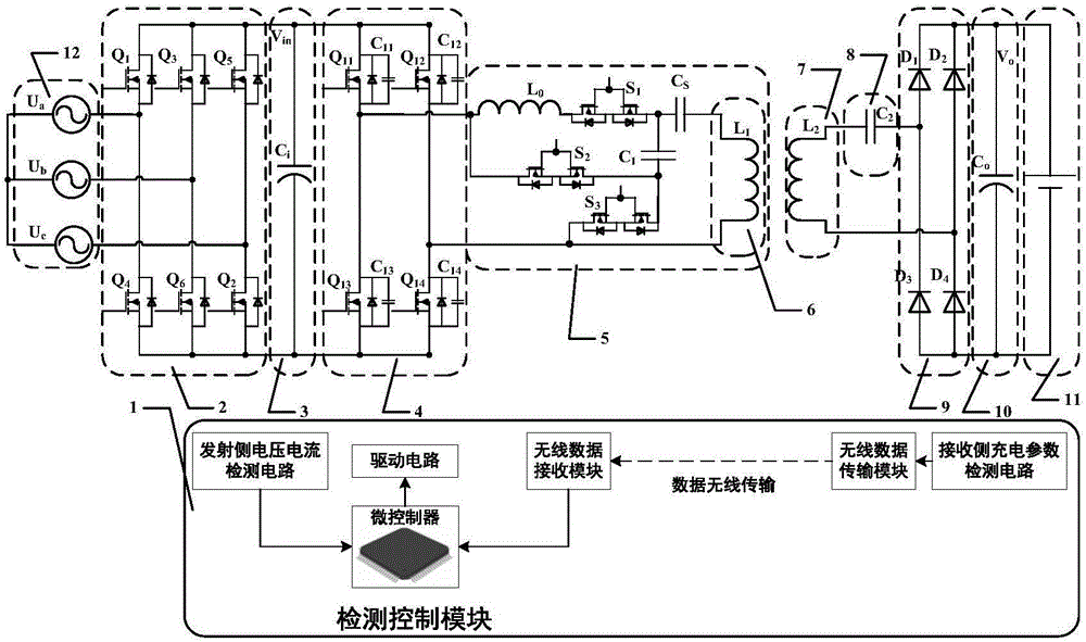
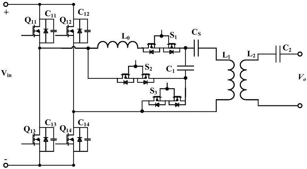
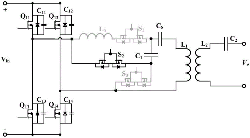
[0038] Such as figure 1As shown, the magnetically coupled resonant wireless power transmission device with variable resonance compensation topology includes a detection control module 1, a rectification module (three-phase AC / DC rectification module 2), a transmitter voltage stabilization module 3, and a DC / AC high-frequency inverter Module 4, variable resonance compensation circuit module 5, coupling resonant coil 6 at the transmitting end, coupling resonant coil 7 at the receiving end, resonant circuit capacitor 8 at the receiving end, AC / DC rectification module 9 at the receiving end, voltage stabilizing module 10 at the receiving end, battery 11. Three-phase power supply12.

[0039] The detection control module 1 includes a microcontroller, a voltage and current detection circuit on the transmitting side, a driving circuit, a charging parameter det...


PUM


Abstract

The invention discloses a resonant compensation topology variable magnetic coupling resonant wireless electric energy transmission device and method. The transmission device comprises a rectification module, an emitting end voltage stabilization module, a high-frequency inversion module, an emitting end coupling resonant coil, a receiving end coupling resonant coil, a receiving end resonant circuit capacitor, a receiving end rectification module, a receiving end voltage stabilization module, a variable resonant compensation circuit module and a detection control module, wherein the input end of the variable resonant compensation circuit module is connected with the output end of the high-frequency inversion module; the output end of the variable resonant compensation circuit module is connected with the emitting end coupling resonant coil; the detection control module is used for detecting charging parameter and input parameter information, and driving the on-off of an MOS (metal oxide semiconductor) tube and the on-off of a controllable switch. At a constant current charging stage, the series / series resonant compensation topology is used; at a constant voltage charging stage, the LCC / series resonant compensation topology is used; on the premise of not changing an electric automobile side receiving end device, the unique requirements of electric automobile charging are effectively met; the efficiency and power optimization of a wireless electric energy transmission system is considered.

Description

technical field [0001] The invention relates to the technical field of wireless power transmission, in particular to a magnetic coupling resonance wireless power transmission device and method with variable resonance compensation topology. Background technique [0002] In recent years, the reduction of fossil fuels and the increasing severity of environmental problems have attracted global attention. Electric vehicles have high energy conversion efficiency and zero emissions, making them an inevitable trend in the development of the automotive industry; large-scale electric vehicles, as mobile energy storage equipment, will also become an important pillar of the third industrial revolution (Energy Internet). However, at present, battery technology has become the biggest shortcoming in the development of electric vehicles, and it is also the root cause and core problem that electric vehicles cannot replace traditional vehicles. The high cost of electric vehicle batteries, lo...

Claims


Application Information

Patent Timeline
Patent Type & Authority Applications(China)
IPC IPC(8): H02J7/02H02J50/12
CPCH02J7/025H02J5/005
Inventor 崔纳新李超群国玉刚张承慧
Owner SHANDONG UNIV
Why Eureka
Try Eureka