System and method for optimizing horizontal tail loads

A technology of elevator and stabilizer, applied in the field of flight control

Inactive Publication Date: 2015-11-25
THE BOEING CO
View PDF5 Cites 9 Cited by
  • Summary
  • Abstract
  • Description
  • Claims
  • Application Information

AI Technical Summary

Problems solved by technology

Additionally, limiting elevator authority prevents excessive maneuverability at relatively high dynamic pressures
Unfortunately, excessively restricting elevator authority based on air speed to reduce tail loading can result in suboptimal handling

Method used


Image

  • System and method for optimizing horizontal tail loads
  • System and method for optimizing horizontal tail loads
  • System and method for optimizing horizontal tail loads

Examples


Embodiment Construction

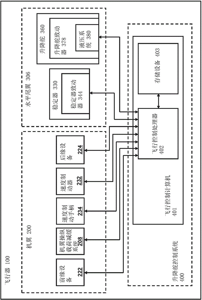
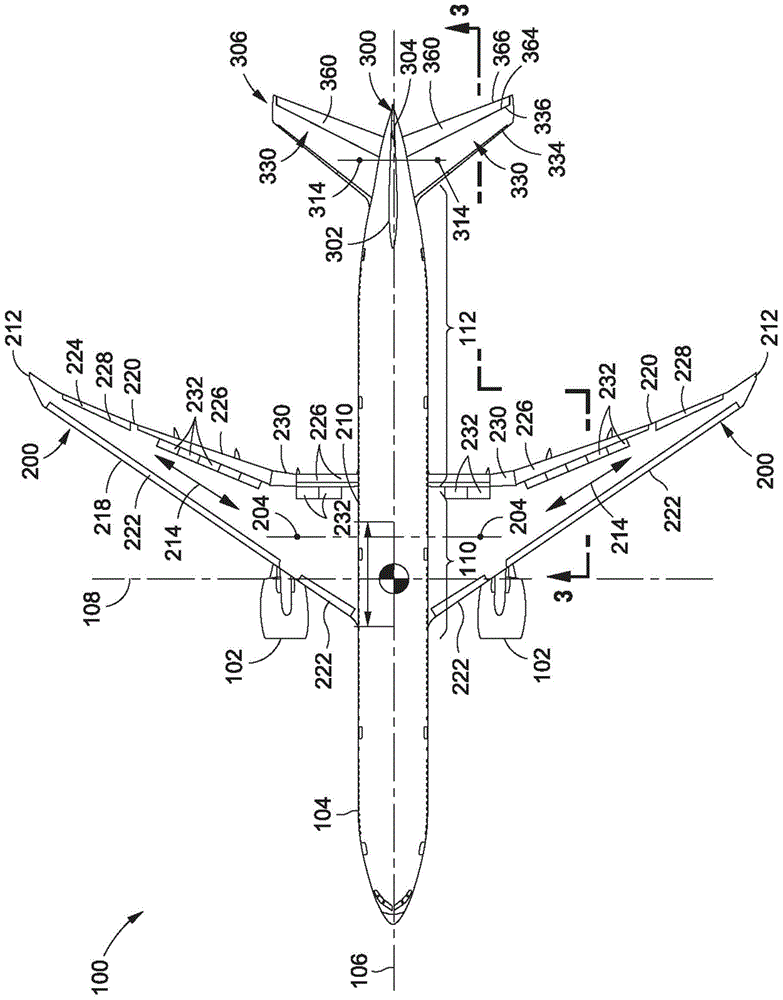
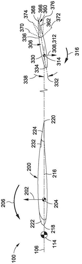
[0025] Referring now to the drawings, in which are shown for purposes of illustration various preferred embodiments of the present disclosure, figure 1 Shown is a block diagram of an elevator control system 400 that may be implemented for controlling the elevators 360 of the aircraft 100 . Aircraft 100 may include a pair of wings 200 and a horizontal stabilizer 306 . Each wing 200 may include one or more leading and / or trailing edge devices 222 , 224 (eg, flaps 226 ) that may be used to increase the lift characteristics of the wing 200 . In some examples, wing 200 may include leading edge devices 222 , such as slats or Kruger flaps. Wing 200 may also include one or more trailing edge devices 224 , such as trailing edge flaps, flaperons 230 , and / or ailerons 228 . Additionally, the wing 200 may include one or more spoilers or speed brakes 232 that may be mounted to the top surface of the wing 200, deployment of the spoilers or speed brakes 232 may be aided as a flight control...


PUM


Abstract

A method of controlling an elevator of an aircraft may include identifying a current stabilizer angle of incidence of a stabilizer of the aircraft. The stabilizer may include an elevator pivotably coupled to the stabilizer. The method may further include comparing the current stabilizer angle of incidence with a threshold stabilizer angle of incidence, and selecting an elevator position limit that is more restrictive if the current stabilizer angle of incidence is greater than or equal to the threshold stabilizer angle of incidence. The method may additionally include moving the elevator to a commanded elevator position that is no greater than the elevator position limit.

Description

technical field [0001] The present disclosure relates generally to flight control and, more particularly, to systems and methods for optimizing empennage loading on an aircraft. Background technique [0002] The pitch control of the aircraft is the control of the nose-up and nose-down pitch attitudes of the aircraft during flight. During a pitch attitude change, the aircraft pivots about a lateral axis extending through the aircraft's center of gravity (CG). Pitch control may be provided by a horizontal stabilizer, which may be located aft of the aircraft's wings. The horizontal stabilizer may include adjustable horizontal stabilizers and elevators. An elevator may be pivotally coupled to the horizontal stabilizer. The angle of attack of the horizontal stabilizers may be adjusted in a positive and / or negative direction relative to the longitudinal axis of the aircraft to tune the aircraft to maintain the aircraft at a constant pitch angle during flight. For example, the ...

Claims


Application Information

Patent Timeline
Patent Type & Authority Applications(China)
IPC IPC(8): B64C13/38
CPCB64C13/16B64C13/503G05D1/0066G05D1/0833B64C13/505B64C13/042B64C13/506B64C13/00B64C5/02B64C9/00B64D43/02
Inventor V·麦姆音
Owner THE BOEING CO
Why Eureka
Try Eureka